Yes I think that would help in mimicking the spring behavior. To be more precise, try to make a face cutout on the plates where exactly the spring is touching and apply elastic support there. I would also suggest you to align your geometry such that springs are aligned laterally to an axis.
Try to minimize your problem. Take only those parts which will play a role in this simulation. Parts which will not be going to have any change should be taken out.
First of all, if your material is similar for those parts which will not take part in motion (thus are bonded) than fuse them. Decrease your number of solids as much as possible. Then I suggest you to import each solid separately and try to create an auto mesh and see which part isn’t meshable. This will help you to find where is the problem. If these parts have same material than I think they can be fused together:
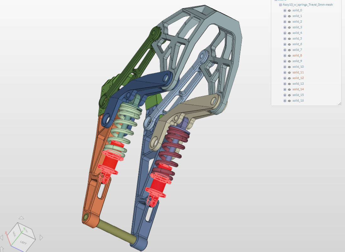
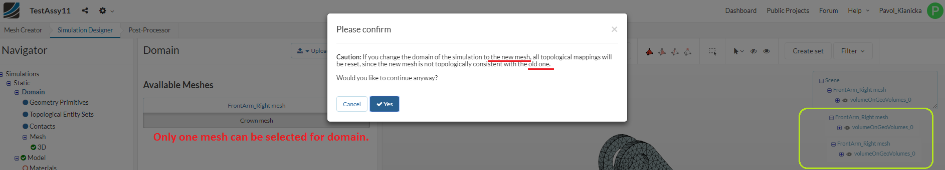
Hi @ahmedhussain18. My idea was to import each assembly part individually into SimScale project, create a mesh for each part, and then build one simulation domain over these individual meshes and setup contacts between individual parts.
Bud it seems it’s not possible, because in Static simulation domain only one mesh can be selected. or am I missing something?
Yes exactly… CAD initially has to be an assembly to work with. Unfortunately, you can’t join meshes afterwards.
So stalled I am. I’ve confirmed that redundant constraints in Inventor Dynamic Simulation that are automatically generated from assembly constraints lead to wrong force and moment evaluation, but it’s like impossible to ged rid of those damned redundant forces to get correct calculations for each linkage pivot and use to them to perform per-part stress analysis.
Along this, I’ve been struggling to make my SimScale simulations work for entire assembly. I found two projects for double-whishbone suspension evaluation, apparently there are several ways of setting up the linkage model in SimScale but I none of my analogies have worked. I tried to implement the same philisophy from each project but so far not so successfully.
The patterns I found are:
1, Structural Analysis of Car Monoshock Wishbone by nwu, which uses Fixed value constraints to allow linkage parts to move.
2, Structural Analysis of Double Wishbone Car Suspension by stadlerj, which uses Remote Displacement constraints to allow linkage parts to move.
My project: TestAssy
1, My first experiment with Fixed value constraints constrainting entire volumes of linkage parts, and took almost 20 hours to end unsuccessfully.
Simulation: Sim3-1spring_volumes_Fixed_value
2, My 2nd experiment with Fixed value constraints constraining only selected faces (trying to copy the original idea) keeps failing after 15 minutes.
Simulation: Sim4-1spring_Fixed_value
3, My 3rd experiment with Remote displacement constraints keeps failing as well.
Simulation: Sim5-1_spring_RmtDsplcmt
Hi @Pavol_Kianicka!
I will contact one of our engineers to have a look at this issue. Deleting the run won’t stop it unfortunately. If that’s a mistake from our side we will reimburse the core hours of course.
Best,
Jousef
Hi @jousefm, in the meantime the simulation run in fact finished (with error). You can see it in my TestAssy / Sim3 / Run5. It took 1.173 minutes.
I just realized, that my assembly simulations may not be working because of improper Contact surfaces selection. I may have misunderstood the Contact relation as a virtual, or general, thinking that even two holes physically apart can be in contact. Setting tolerance OFF doesn’t help anyway.
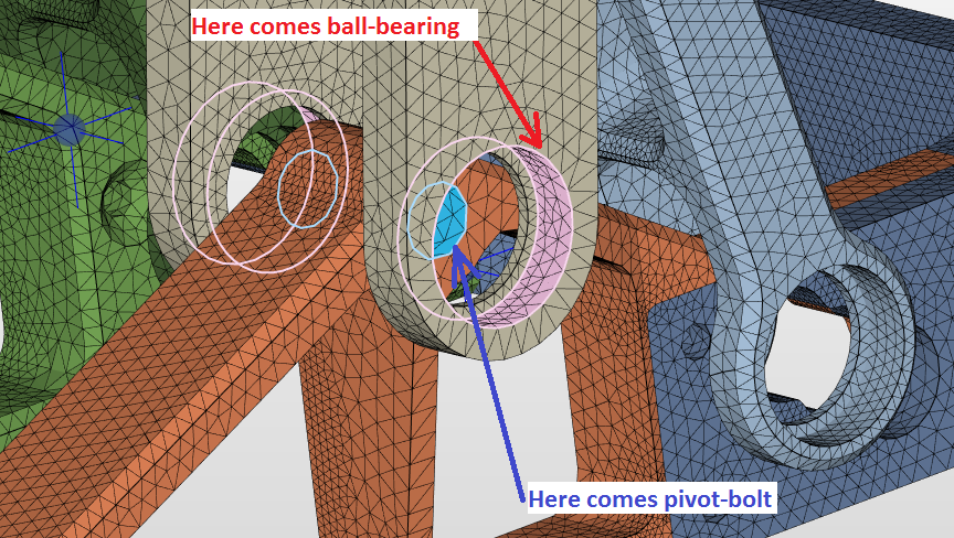
I think, that surfaces in Contact must have their normals against each other. I shouldn’t put in Contact two holes, which are in reality connected by pivot bolt and ball-bearing.
I wanted to avoid drawing the pivot hardware, putting all pivot bolts, washers and even ball-bearings in my assembly and having to set-up all those Contacts in SimScale. It seems that I will have to add at least the pivot bolts into assembly because they will create situation of two surfaces facing each other.
All other projects that I’ve seen here used either some sort of sliding surface pivots (ball-joints of double whishbone suspension) or a pivot bolt in one of the linkage parts.
1, Is my thinking here correct? Am I to add at least pivot bolts into assembly joints?
2, Is pivot bolt enough? There will be void space between pivot bolt on one part and ball-bearing housing on counterpart.
3, Is adding a ball-bearings into assembly worth of higher computational demand? Does it make significant difference in Static-Nonlinear simulation in terms of analysis accuracy?
Screenshot of one of the linkage joints, with surfaces selected for the SimScale Sliding Contact relation:
Hi @Pavol_Kianicka!
What I think is that the simulation that had over 1000 minutes runtime had the problem of wrong master-slave assignment causing the time to explode.
Best,
Jousef
Hi @Pavol_Kianicka,
The only way I have used the sliding contacts is when the two surfaces are in contact with each other. I was able to create an assembly with the orange and tan parts (2 parts total) in your image above. I applied the sliding constraint and a load and I was able to get the problem to solve but the results looked incorrect. So my guess if the sliding contact cannot be applied in this way. Also with the tolerance off on the Sliding Contact this will be driving up your solution time a lot. this could explain why your run time is so long.
I would suggest modeling some sort of bushing to connect your parts together, keep it as simple as possible. In the image above you want something that will be touching those three surfaces. Unless your interested in the stress in the joints I would not model your actual hardware, this will just complicate the analysis. Do not model ball bearings!  You can adjust the stiffness of the “bushing” part to better match the ball bearings buy changing the material properties. If you want to.
A few things to keep in mind. the sliding contact is a linear constraint so its only valid for “small” rotations. If our parts rotate too much then the results will be off.
The Sliding Contact constraint transfer the loads over the entire 360 degrees while in real life the loads are transferred across less than 180 degrees. If your looking at stresses around the connection points your results will be off. If this is what you are interested in then Physical Contacts may be needed.
I hope this helps a little. You are trying to tackle a very interesting problem.
Christopher
Hi @cjquijano. Thanks a lot for your effort and asnwer.
I did thought that simple Sliding Contact is not a correct contact to transfer loads in linkage joints right because I need to simulate them at 180° range, and not in 360° range. I just thought that using Physical Contact would drastically increase computation time.
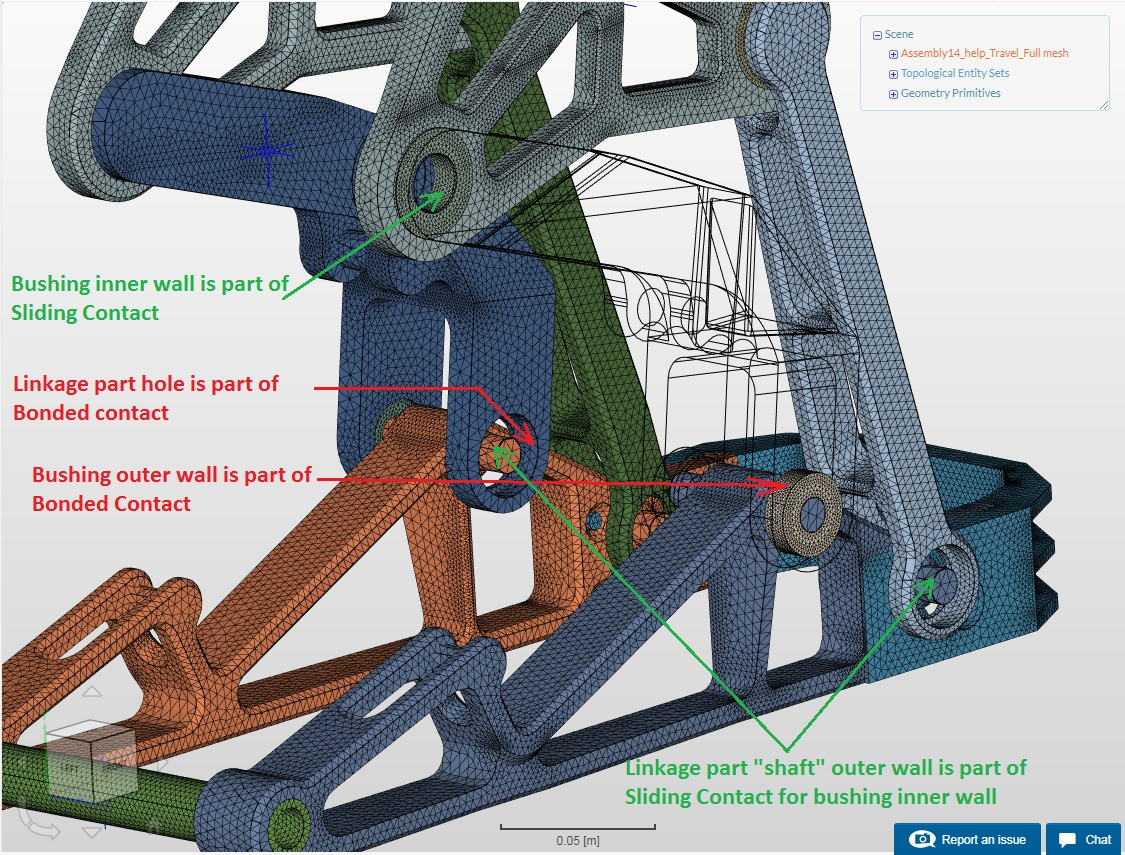
Anyway, I modified my assembly and linkage parts. I inserted cylinders into ball-bearing housings as a sort of bushings, and replaced pivot bolt holes with pivot shafts to support bushings. I noticed there is an interference between three parts due to edge chamfer but I cannot repair it now.
So, I setup zilion of topological entities, half a zilion of Bonded and Sliding Contacts, and with inspiration of one double wish-bone suspension project, I specified rotation using Remote Displacement boundary condition in only top-most pivots. The coil spring stiffness is mimicked by Force load. We’ll see if all of this helped, it runs 30 minutes now already.
Project: TestAssy14 help w bushings
Idea of my bushing solution.
Well. I did three runs (with PETSC and MUMPS solver, with 4 and 16 cores, automatic and manual timestep) and they all ended due to error after 61 minutes, and there’s nothing in error log because “Result recovery failed.” 
Surprisingly, I have found out that @anon94132533 viewed my earlier project in February and successfully did the calculation by using 32 computing cores. So I copied my project from him :-), and have been doing some experiments that are little bit strange.
@anon94132533 didn’t change anything in my simulation settings, just changed solver to MUMPS with 32 computing cores. I then added the 2nd pair of elastic supports to mimick the 2nd coil spring, tried replacing Force load by Remote Displacement condition to drive the linkage, but I still get extremely low stresses within the linkage.
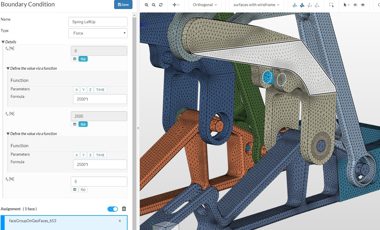
The intended coil-spring stiffness is 44N/mm per coil. 1 spring is mimicked by 2 elastic supports that I placed on a circular support plates of 53mm diameter. Since the real-world coil spring is touching the support plate only by half of its perimeter, I multiplied the elastic support stiffness by 5.8 because the support area under coil-end is 6x smaller than entire support plate.
22N/mm per coil-end multiplied by 6 is cca 130.000N/m.
I have to take into account the force that has been accumulated in the spring before the spring reached its maximum load and linkage reached its final point. The “preload” of the spring. So, 22N/mm per coil-end, multiplied by 57mm of spring stroke, multiplied by 5.8 is cca. 7.400.000N/m. I put this number into spring stiffness field of each of the four elastic supports.
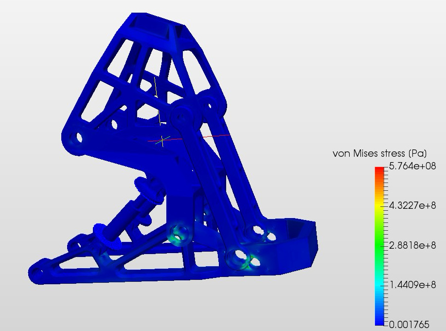
And the result of calculated Von Mises stress is the same with or without the preload, Which is very strange, because I have put the fixed support at top most part of the assembly, so the input force of 1.800N with high spring loads must be acting against this fixed support. There must be much more stress in assembly.
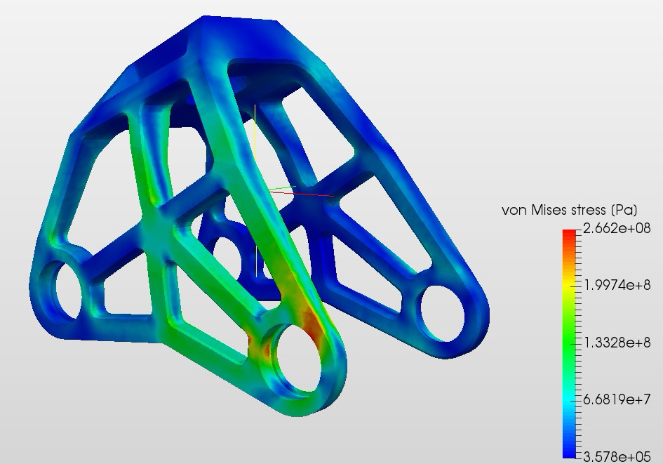
When I simulate stress analysis of the top most part with forces and moments that Autodesk Inventor calculated, the stress is absolutely different to what I have “simulated” using elastic supports in assembly.
Sole part simulation:
Assembly simulation with all loads I could think of:
Hello @Pavol_Kianicka,
I think the only way to realistically model the assembly with SimScale is to use the full assembly including the bushings and the spring coil. To reduce the overall model size I would advice to take advantage of symmetry (in case the loading conditions are symmetric) and use only half of the model.
The limitations at the moment are the following:
- the elastic support constraint can not model a spring between two parts, only a sprint between a part and the “ground”
- there is no simple way of defining a “hinge” connection, the way to go would be using a physical contact (maybe a sliding contact for small relative rotation)
If I have some time I will have a look at your project, but realistically this won’t happen before the weekend.
Best,
Richard
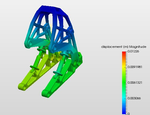
Just a small update. I replaced 4 elastic supports mimisking 4 coil-ends of my 2 springs, I replaced them with 4 Force loads of the same magnitude multiplied with shock eyelets vector and small miracle happened after 30minutes. Eventhough, the displacement is weird, because the two droputs were meant to move only 1mm.
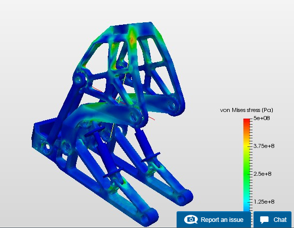
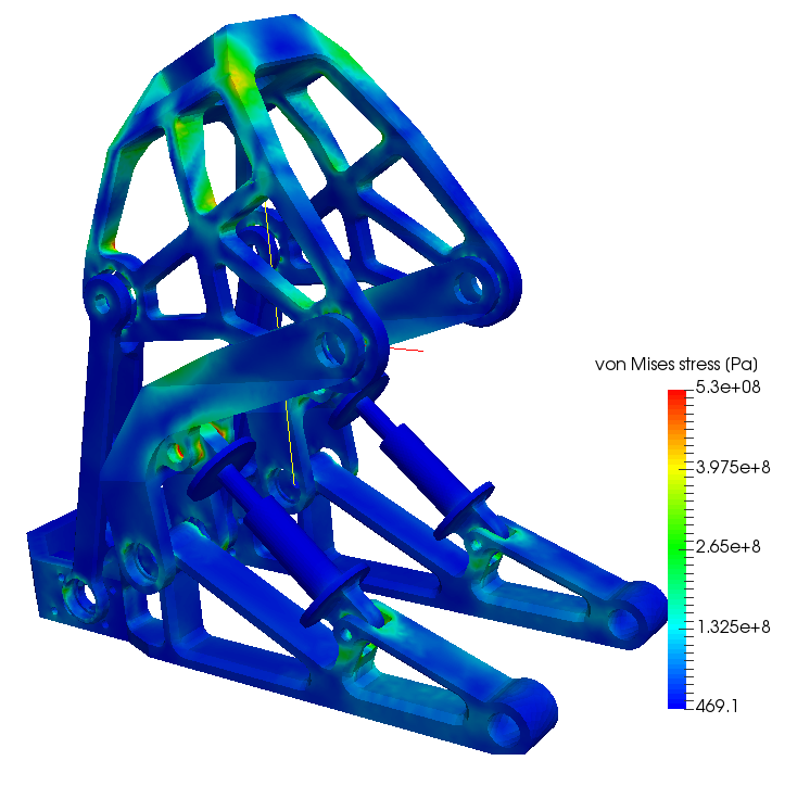
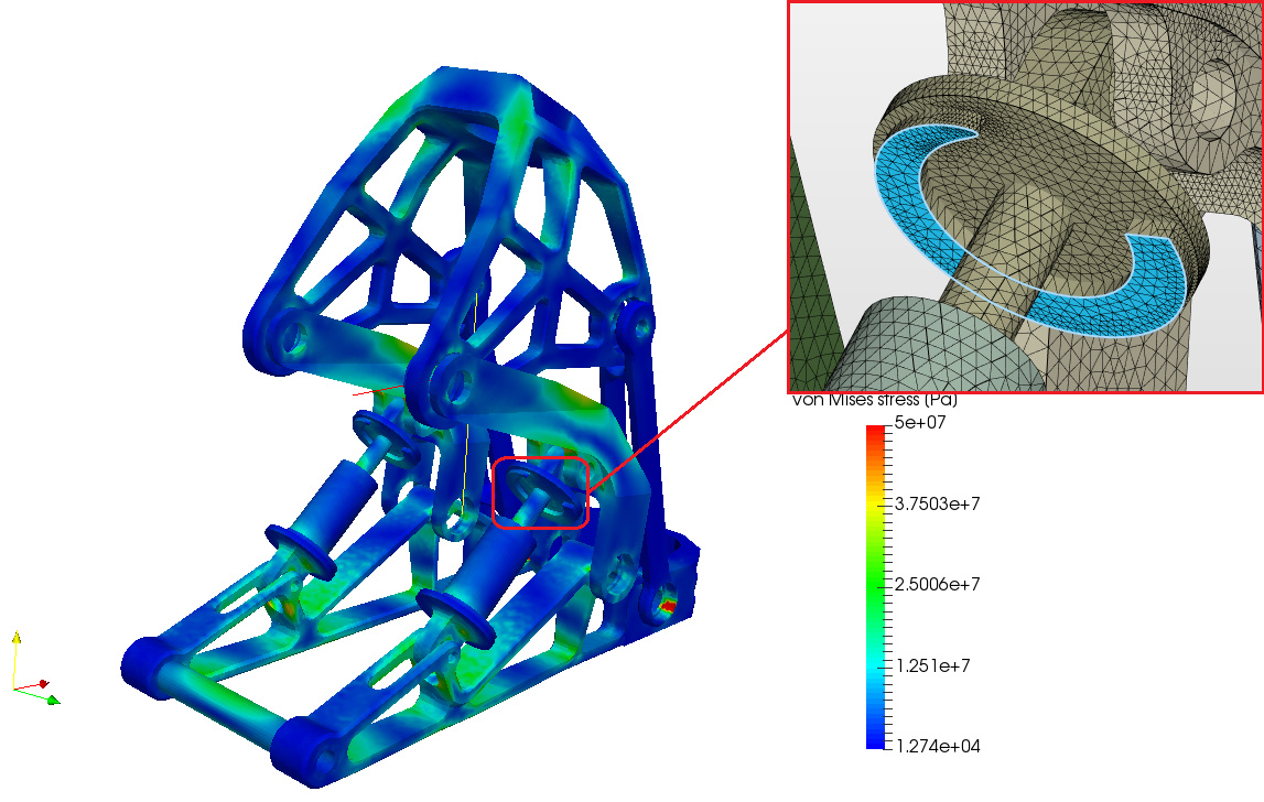
After correcting contact type (from Bonded to Sliding) at one of the coil-over strut eyelets, the result looks MUCH better as far as for Von Mises stress.
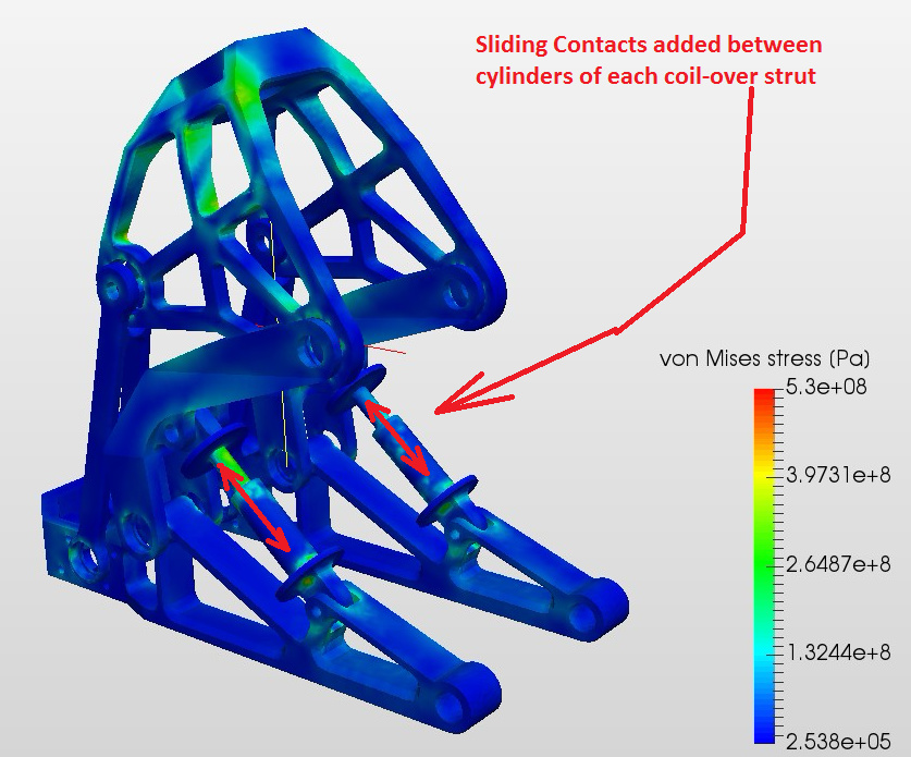
Already running another simulation with Sliding contacts added to cylindrical halfs of the coil-over struts.
With the Sliding Contacts added into coil-over struts, the assembly is much less stressed and there are less stress peaks.
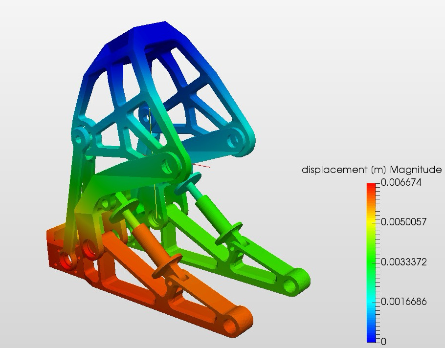
The too asymmetrical displacement is weird because the assembly is setup and loaded symmetrically, but I don’nt mind it because I have another SimScale project working together with and axle that tightly connects the two sides of upright fork.
Good job! your final simulation results (which are not stated here) looks also quite good. They are perfectly symmetric. But what I can see so far are the stresses around the contact areas of the coil-over struts. That can be due to use of sliding contact. Since sliding contacts are not made for larger deformation. After the small deformation level is reached, it nearly acts like a bonded contact. You can test another model using physical contact instead and see if there exist a huge difference or not. If there is not a huge difference then you can of course go with sliding contact which is faster and easier to handle.
Unfortunately changing the solver to nonlinear for physical contact will delete all the assignments. You have to redefine everything from scratch. But just a suggestion: you don’t have to set all the contacts separately, you can set them in 1 or 2 sliding contact definition. In that case make sure that a low tolerance value is set under sliding contact otherwise far defined slave face will also come in to contact with other master surfaces.
Just a hint for future simulations: Try to initially set the simulation with nonlinearity set as true. Then you will have flexibility to turn off separately the nonlinearities for example geometric nonlinearity etc. to make it a linear analysis. And then if you want to use nonlinear features then you will not loose anything 
Best,
Ahmed
Hi @ahmedhussain18. Thank you for having a look at my simulations. I’m currently doing several various setups, linear and nonlinear, with different geometries. I will be deleting some of the projects, because I’m starting to loose myself between them and some are meaningless. I was struggling to make the assembly simulation actually work, to get it finished successfully.
I found, that it’s best to turn OFF the tolerance for the Sliding Contact. For nonlinear simulations I now use only Absolute option for Convergence criteria type, and using 32-32 computing cores.
I now moved to assembly versions where the left and right side of upright arm are connect by wheel axle. It’s amazing how this connection stiffens entire assembly.
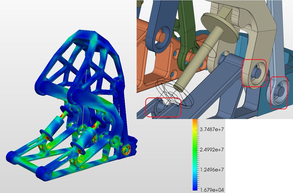
I prepared assembly with coil-end contact-area extruded from the support plate, to have precise area for placing the correct spring stiffness force. The result is very interesting, assembly is very slightly stressed.
And I’m comparing it to another assembly where pivot shafts are mimicked by extruded cylinders to provide surface that is against the mating hole surface (that was at time when I thought the two surfaces in SimScale Contact must be have their normals against each other). And this version gives quite different stress distribution
No pivot shafts, just very distant Sliding Contacts.
Pivot shafts mimicked by extruded cylinder surfaces to face the pivot hole surfaces.