I am doing a Conjugate Heat Transfer v2.0 on a reactor design to test different geometries on the most efficient heat transfer. Therefore I have a geometry with 3 regions which include the solid reactor, first flow region where hot pyrolysis gas is flowing and an inner flow volume consisting of air to check the heat up.
The outside reactor walls are set to have an adiabatic boundary conditions with no-slip conditions on the interface with the flow region. The inner walls of the solid region do not have a specified boundary condition. The outer flow region (pyrolysis gas) has two velocity inlets of 4 m/s at 800 degrees Celsius and a pressure outlet of 0 bar gauge pressure. The solid reactor is initialized at 200 degrees C, the outer flow region at 300 degrees C and the inner flow region at 100 degrees C. Everywhere pressure and velocity are initialized at 0.
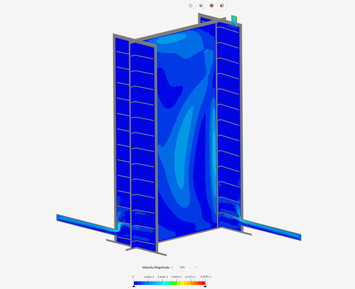
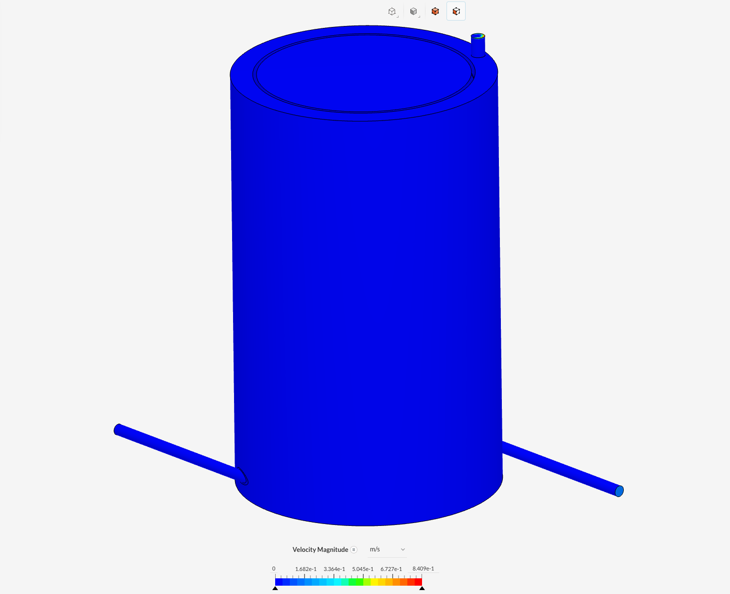
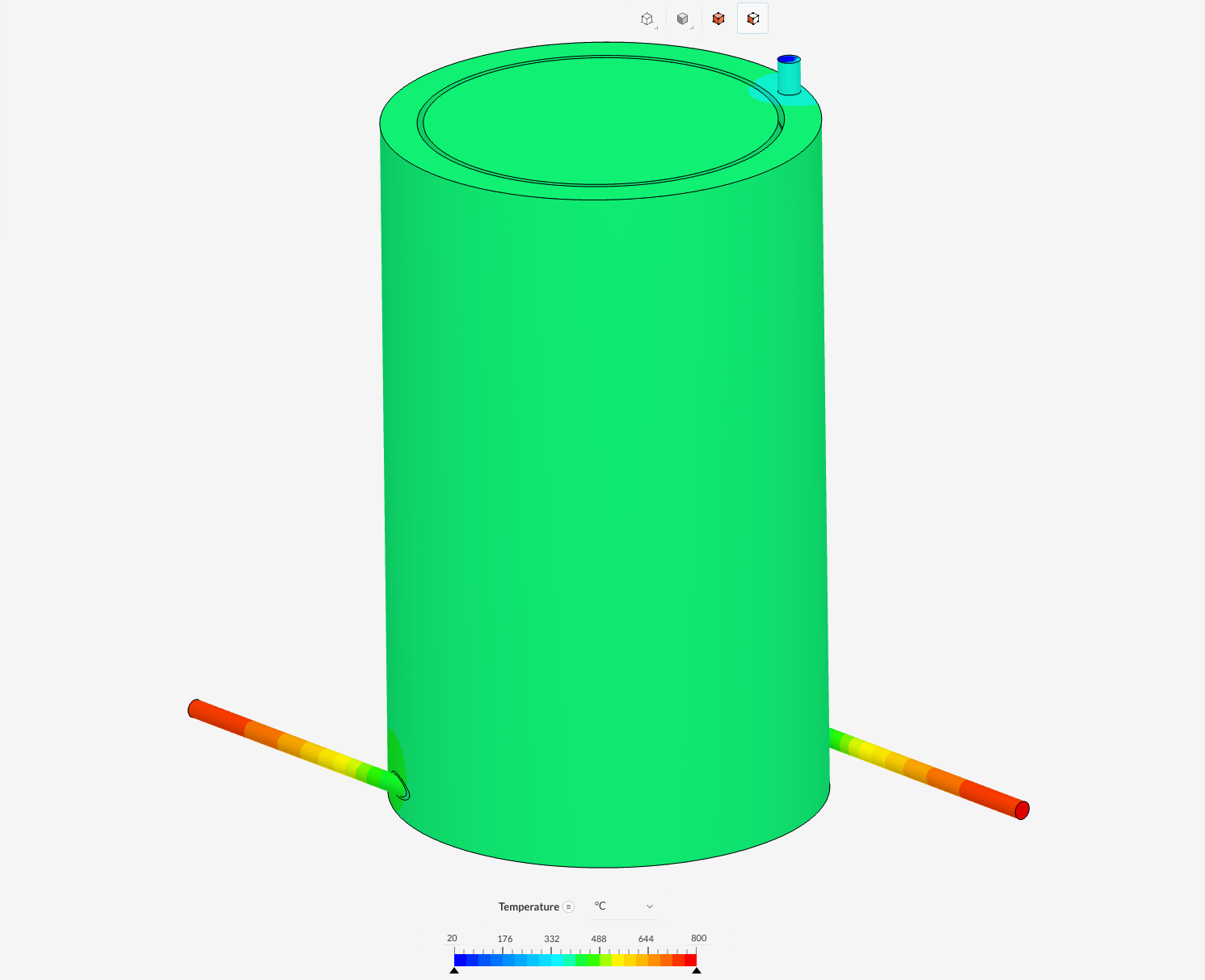
I did 1500 iterations at steady-state conditions but the results are not looking promising. The velocity magnitude is 0 in almost the whole outer flow region. When looking at the temperature profile it can be seen that the pipes where the gas is entering show a temperature gradient towards the reactor from 800 degrees C to around 400 degrees C. This is strange as I set the outside walls to be adiabatic and thus no heat transfer. It seems as if the entering gas is not getting much further than the inlet pipes. Can someone perhaps help me explain this or give feedback on my setup? I cannot come up with what’s wrong myself.
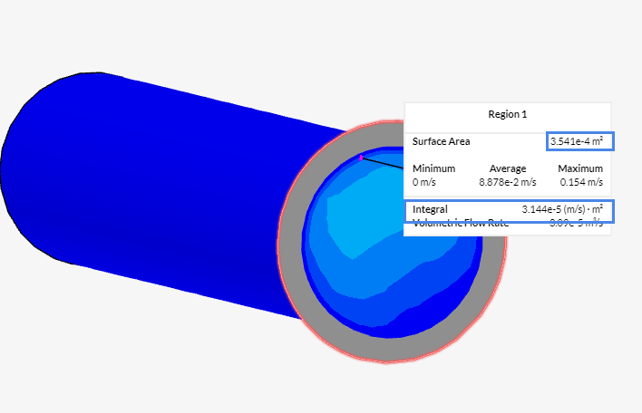
having a look at your simulation I noticed that you defined a volumetric flow rate of 3.5e-5 m/s. having a look at the surface area of the inlet it results in a flow velocity of ~0.1m/s which is seen in the simulation.
I would recommend you switch to a velocity BC definition or scale up the volumetric flow rate to 1.4164e-3m³/s. That will result in a flow velocity of 4m/s.
Thank you for having a look. Initially I set the boundary conditions of the simulation as velocity BC’s and the results can be seen in Run 1. However, as I was not sure whether I did this, I did another run (run 5) with also velocity BC’s. I still don’t see any velocity magnitude when looking at a cross-section of the reactor. The temperature gradient is the same as with the earlier runs. Do you have any other suggestions or ideas what it could be?
Sorry for the delay. I see that your velocity field is not 0 but very small (as shown below), maybe because of the geometry conditions (like inlet diameter, position, etc) or something that I’m missing. But please let me pin one of our CFD specialists who may help you in this kind of detail.
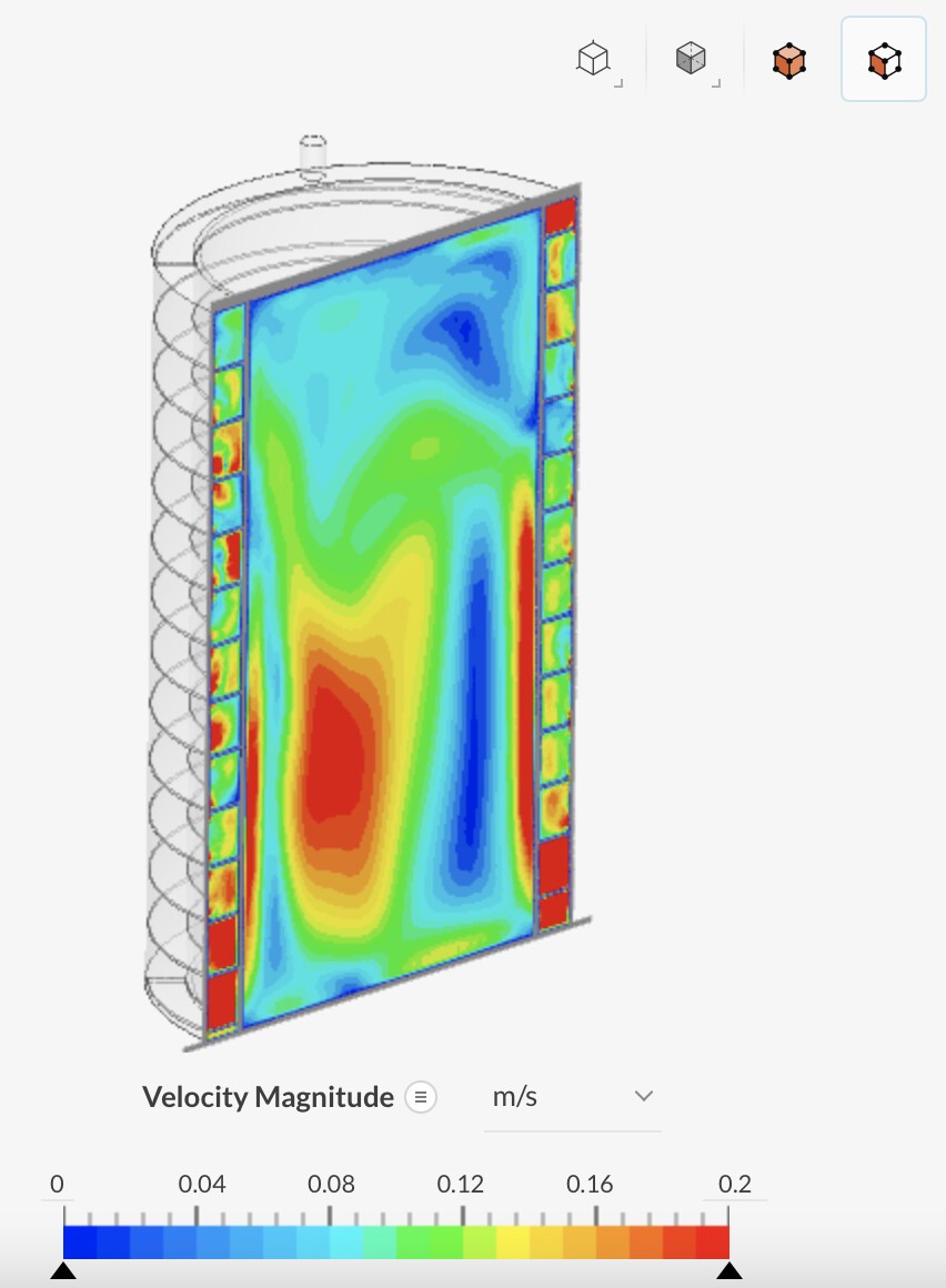
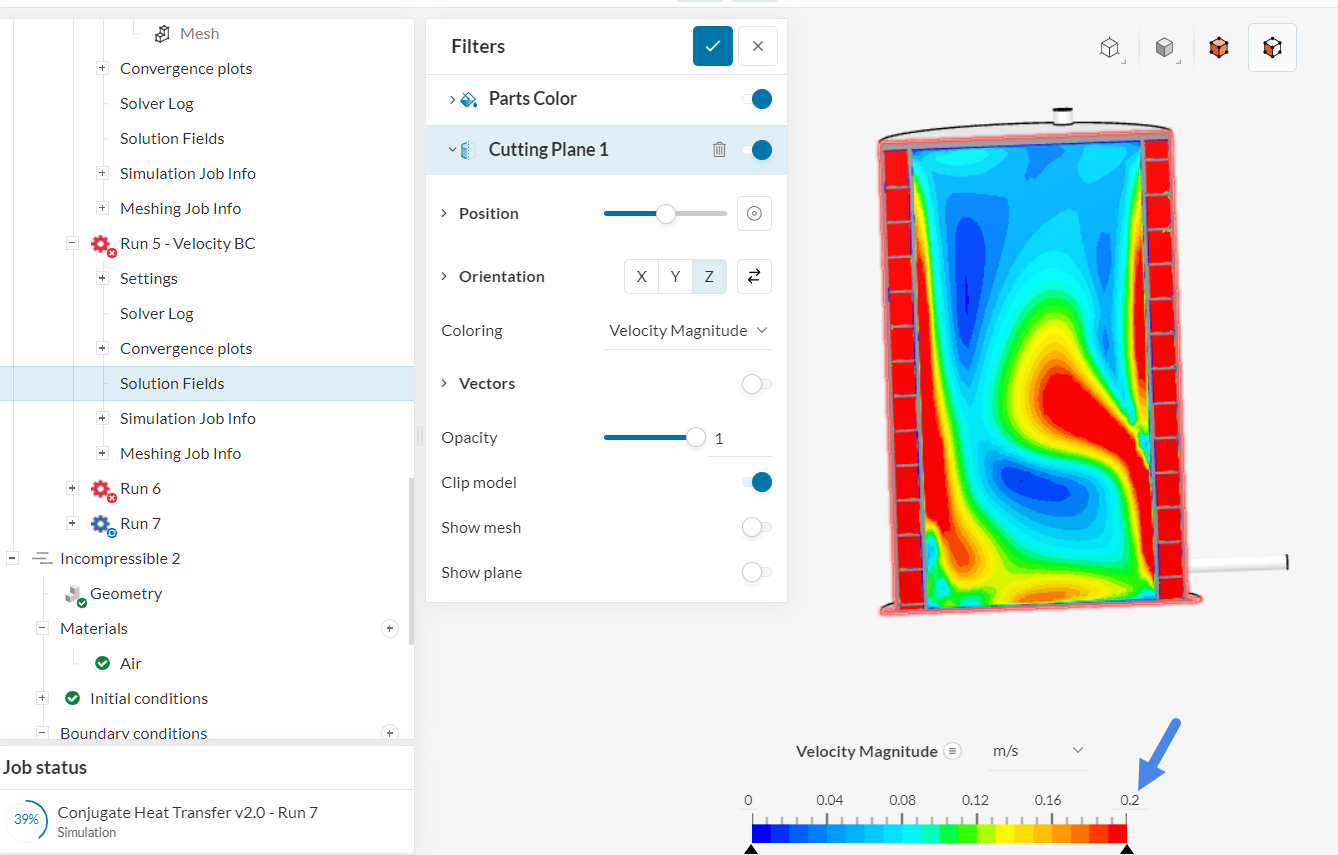
Even in Run 5 (which diverged), you still have a non zero velocity inside of the domain. Perhaps the upper range of the velocity might give you an impression that the entire domain is at 0, but if you adjust the upper range, you’d get more visibility of the vector field:
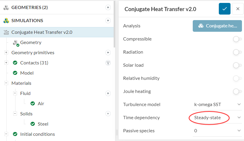
When looking at the setup, I see that you have 800 °C at the inlet for both inlets, there are no other heat sources/sinks in the domain. Furthermore, all external walls are adiabatic.
Since there is no heat being added or removed from the domain, the steady-state result is going to be 800 °C everywhere (i.e. isothermal flow).
If this is indeed the case, the best approach would be to run an “Incompressible” simulation with adjusted material properties.
If you are looking to study a different type of condition, for example, having a transient run with the outer flow region domain heating up the internal fluid volume, then you’d have to adjust your setup strategy. Keep in mind that transient runs are much lengthier than steady-state ones. Find here some initial notes on the transient run topic.
Thank you for your comments. Adjusting the velocity range was very helpful. I now also realized the magnitude of the velocity is much lower than in the inlet because the surface area of the flow channel increases.
It’s true that I have selected adiabatic walls and thus no heat being added or removed from the domain. The goal of the simulation is to see how effective the heat transfer is from the outside layer of the reactor to the inner volume. That’s also the reason that there is an inner fluid volume. This is the first simulation but when this one works properly, I want to test different spiral geometries and evaluate it that has an effect on the heat transfer to the inside volume. Based on your recommendations, I guess I have to switch to a transient run. Thank you for your help.