Hello SimScale users,
Most of you on SimScale may come across the intersecting elements problem while meshing a geometry using Tetrahedralization meshing algorithm. Well there could be several reasons for this cause but most of the time it’s due to complex or non-cleaned geometry. Now what does a clean geometry mean? It means that you have to simply your geometry enough so it could be meshed easily. Since meshing is just an operation to distribute the geometry in to smaller portions which may fail on very small or complex faces.
So in short, most of the time downloading a geometry from a CAD providers such as [GrabCAD] (https://grabcad.com/) and uploading it directly without modifying it leads to meshing problems since those geometries were not made specifically for simulations. In order to make it work, one have to simplify them a lot by removing small details.
Below there are two problem cases which describe this cause and a possible solution for it.
Case 1:
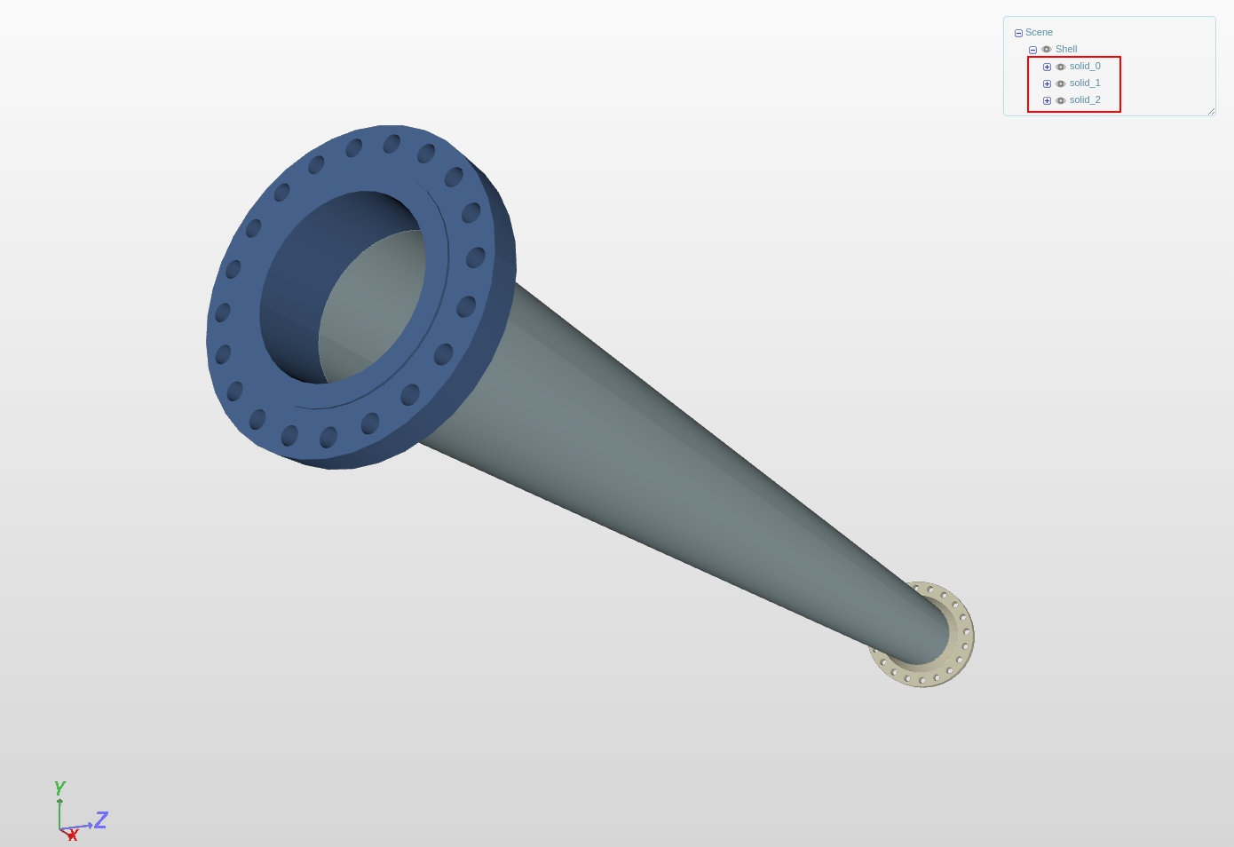
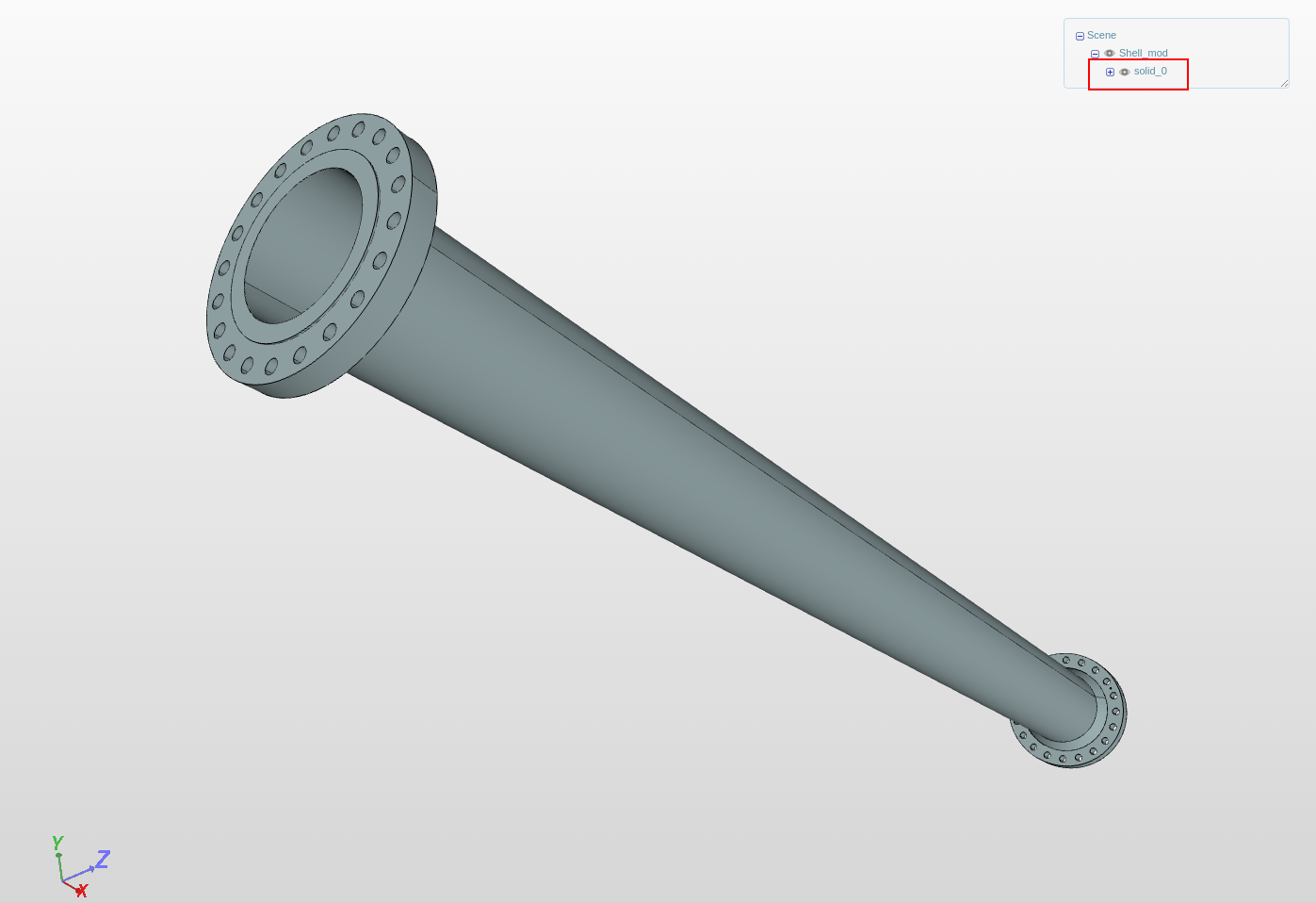
The first geometry we are looking at is shown in the figure below. There are three solids in geometry whereas normally a pipe like this can be represented by a single solid until and unless one need to consider different material for different solids. Therefore, one idea would be to merge them to a single solid.
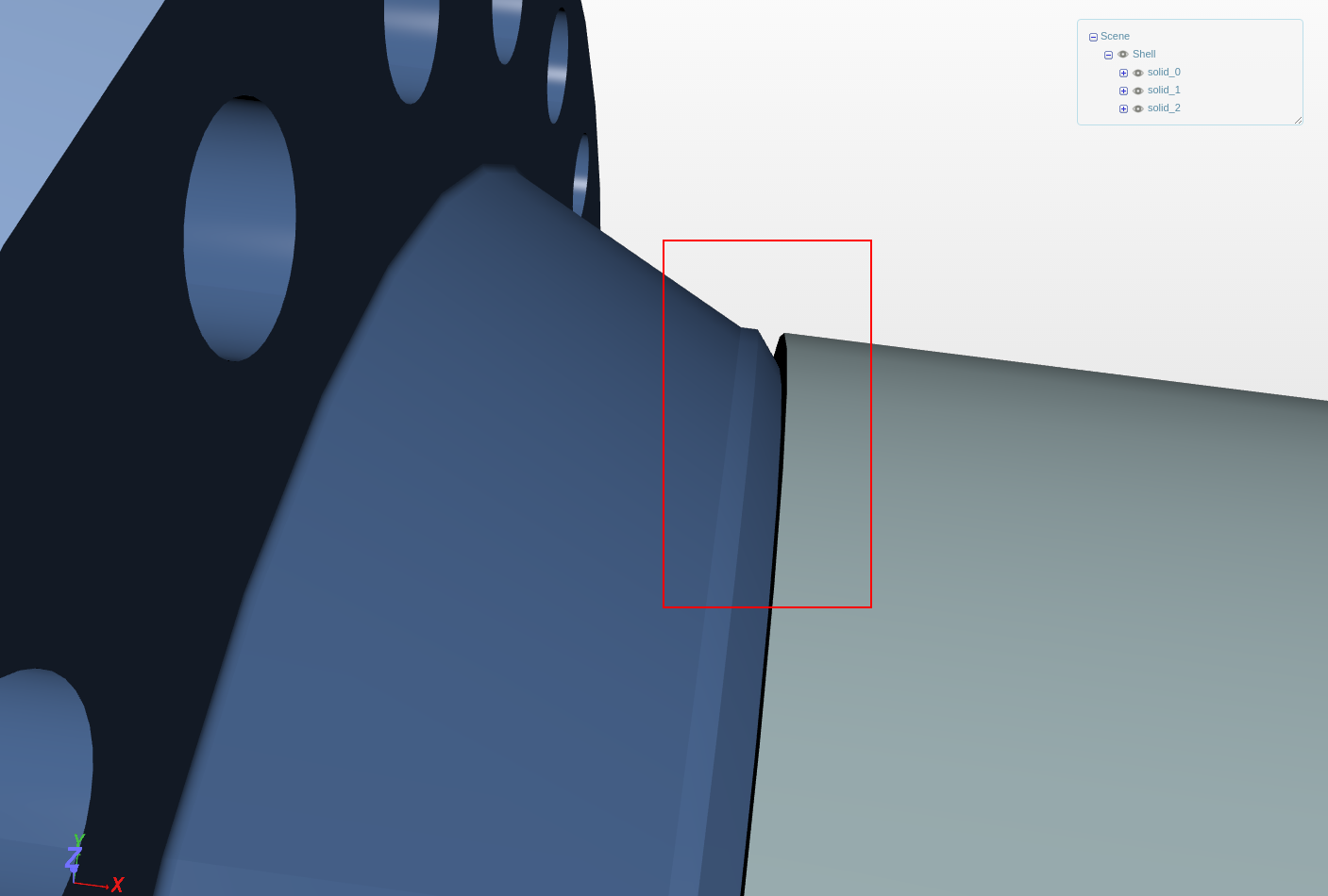
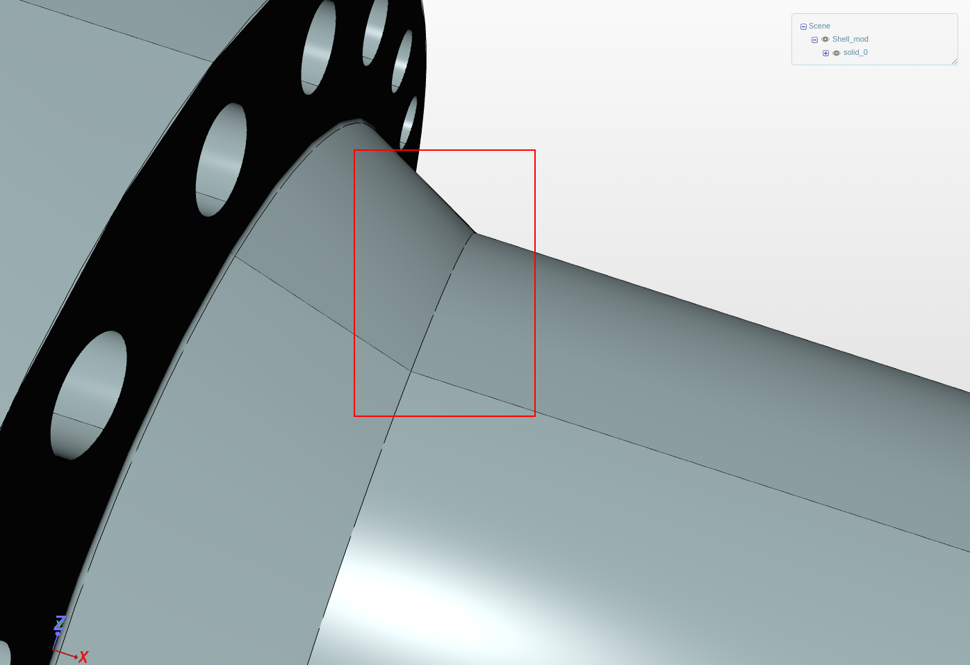
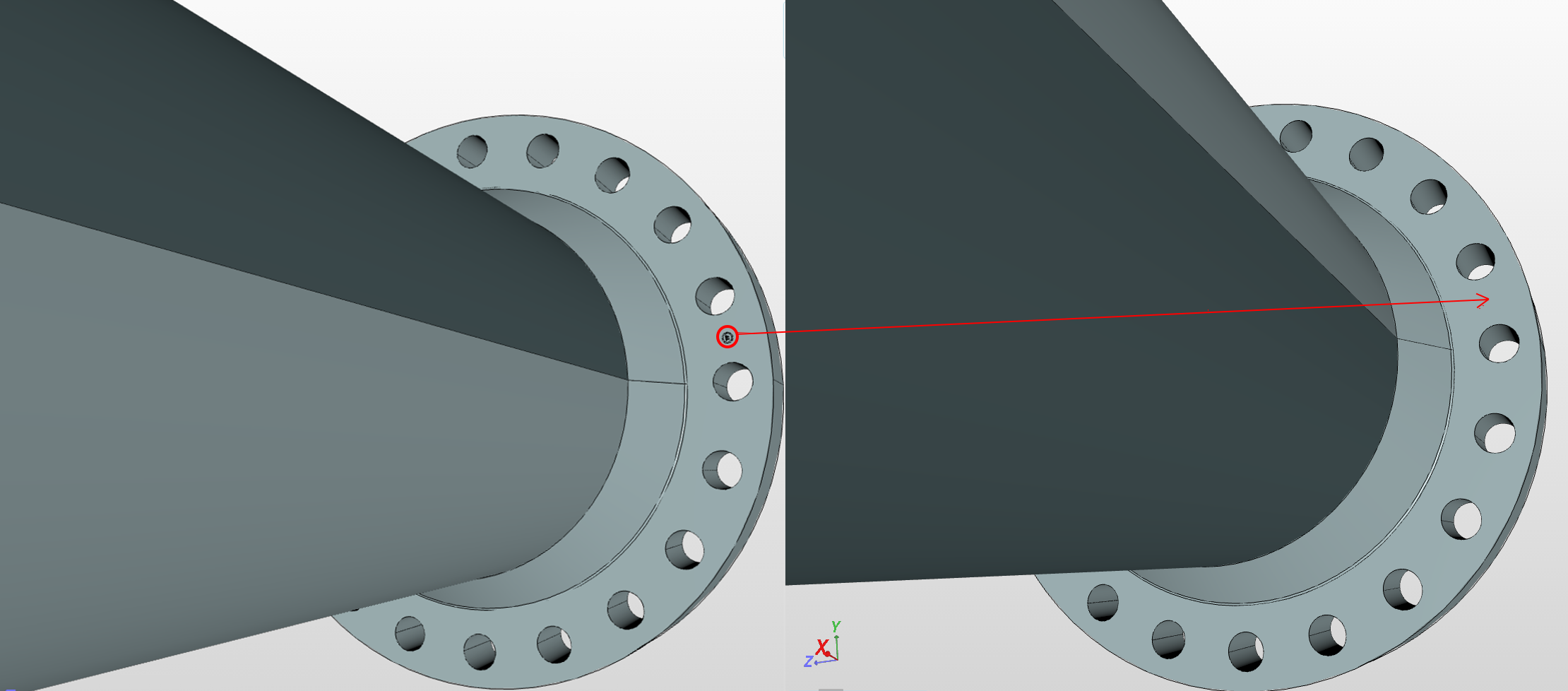
Secondly, if we look more closer to the geometry it looks like that the connection of one side solids with pipe is quite odd which can further be solved as shown in the figure below.
Let’s ignore all this since we really need to know if we can mesh it or not, so I tried to mesh using Fully automatic tetrahedralization with both 2 - Coarse and 4 - Fine settings but end result was a failed mesh. The meshing log says something this at the end:
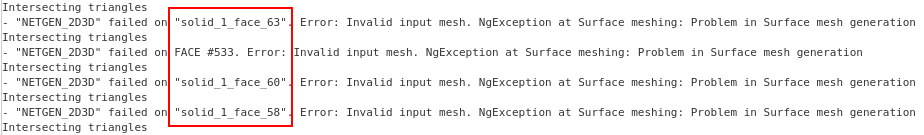
It says that the solid_1_face_58/60/63 has intersecting elements. If we isolate these faces from the geometry, we get something shown in the figure below.
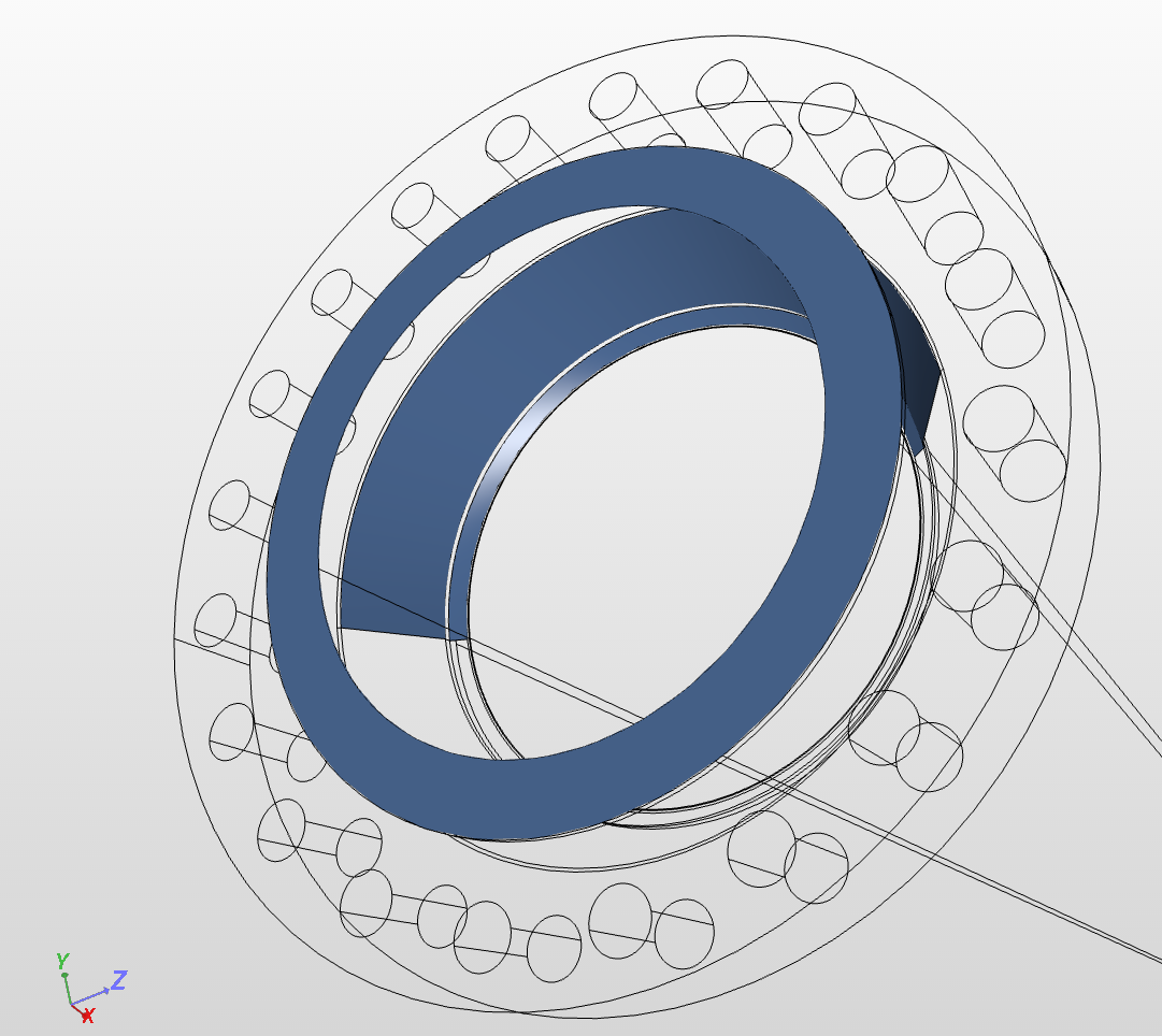
These are the faces where we exactly have this problem. Seems like the already problematic considered faces, right? Now to solve this, I managed to remove some odd fillets and merged the solids. The final result look like this:
If we look closely now to the same portion, it looks quite smooth and simplified, see the figure below:
Looks like we are good to go, so I meshed it again but wait.. “the same error??” Now this is not good. Even simplifying didn’t help. But why? to find out let’s see the meshing log again.
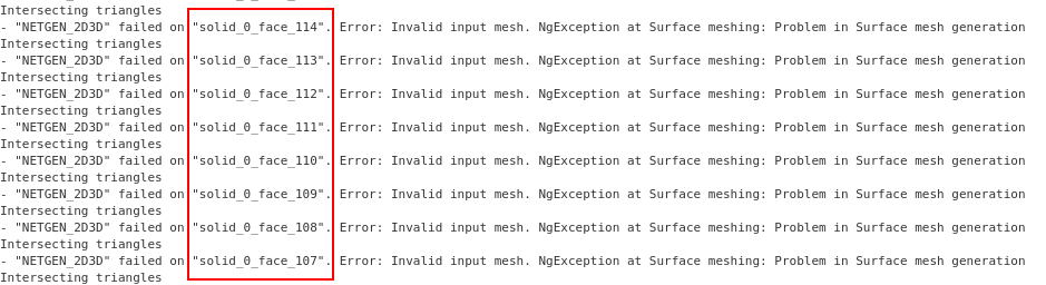
This time there are many faces (even more than what is shown in above figure) mentioned as problematic. So I did the same procedure, I isolated these faces and this is what I got:

Well this doesn’t look that good, If I now show all other faces this is how it looks like:
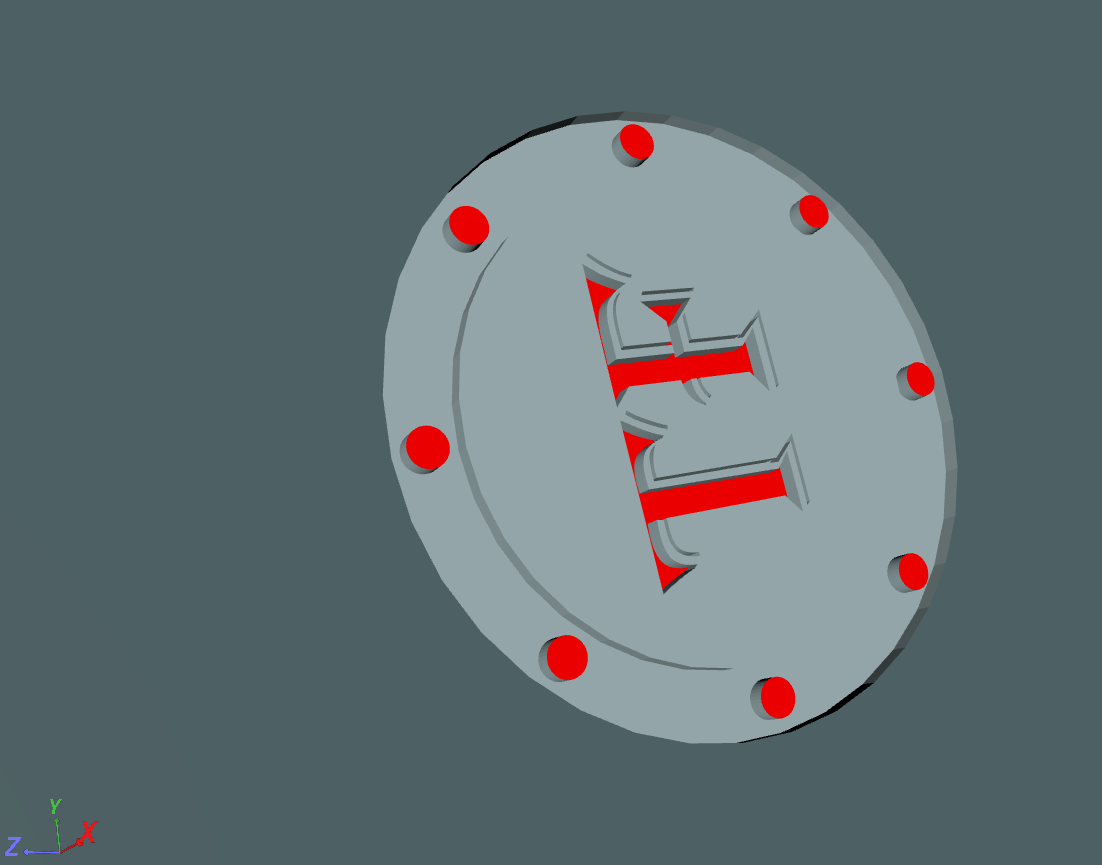
So there is a small embossed sign on this geometry, pretty hard to find right? but reviewing the meshing log makes it easy to find. So now the final thing will be to solve this problem. So I removed this sign and re-uploaded the final cleaned geometry. The figure below shows the difference.
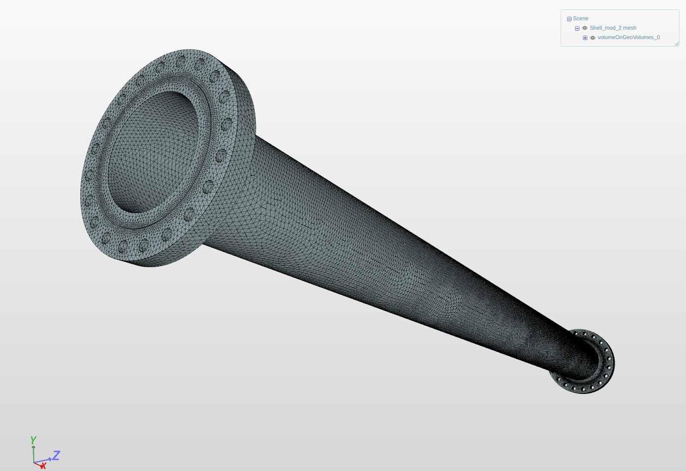
Now it’s time again try to mesh it, using just Fully automatic tetrahedralization with 3 - Moderate meshes it quite easily. Figure below shows the outcome.
Case 2:
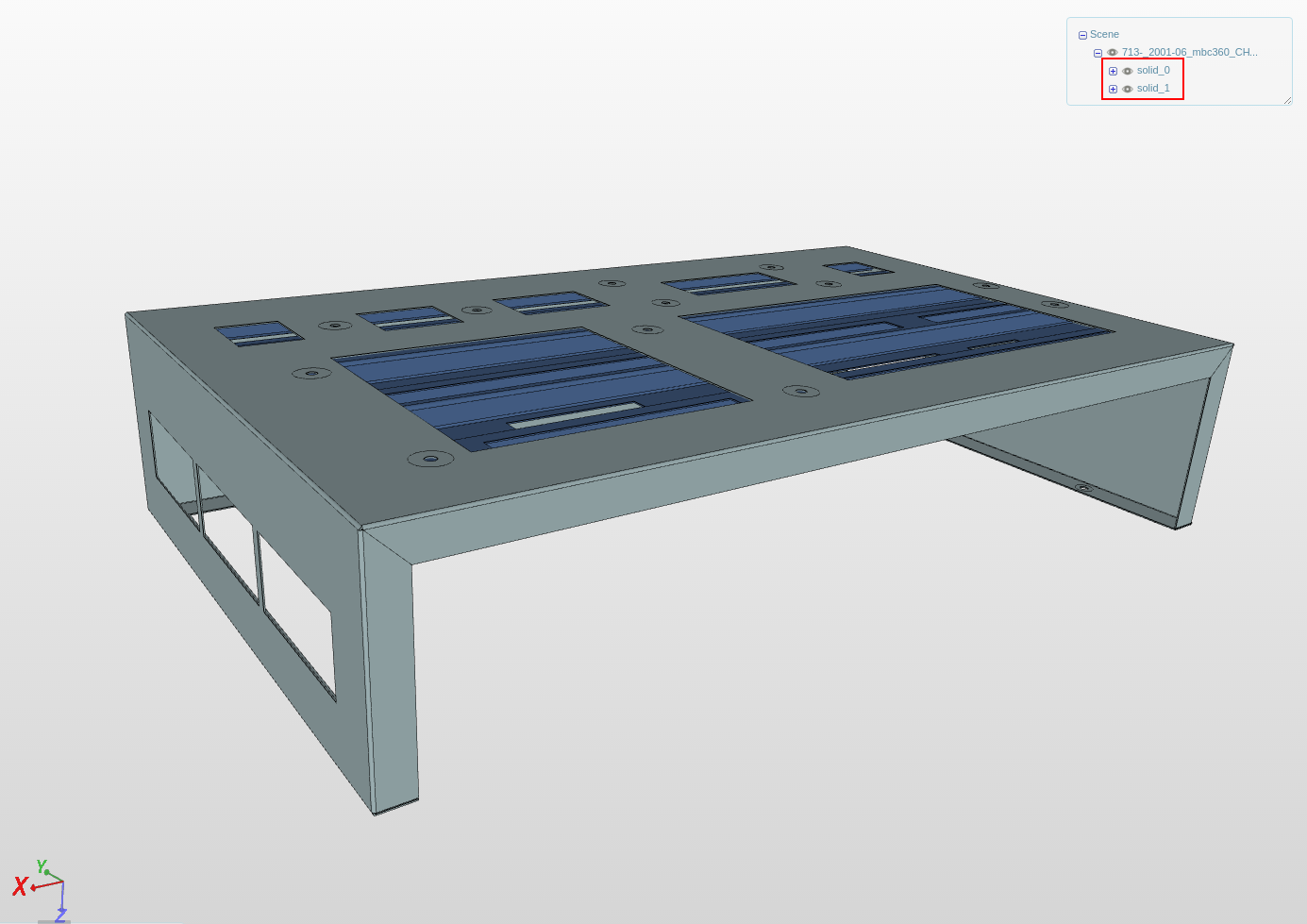
The second geometry we are looking at is shown in the figure below. There are two solids in the geometry and they look quite fine overall.
So I started the mesh operation but ended with an error, which says at the end something like:
![]()
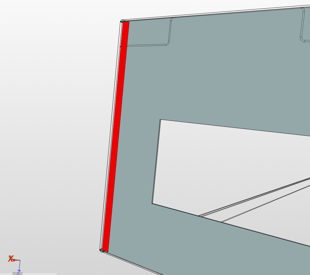
It says that the intersecting elements are due to solid_0 where it has the overlapping boundary mesh. It is not pointing out explicitly about the overlapping faces since it’s quite difficult to track them. Therefore, we have to look ourselves in to this problem. I looked closely by hiding each face one by one to finally find the overlapping faces. The overlapping faces are shown below:
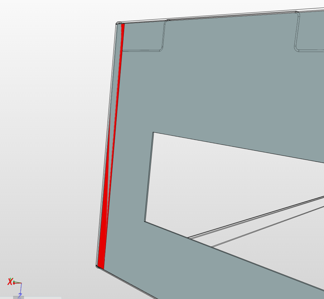
The small semi red highlighted face is an extra face overlapping the large non highlighted face. Therefore, in order to mesh this geometry, we have to remove the smaller face. The figure below shows the corrected geometry:
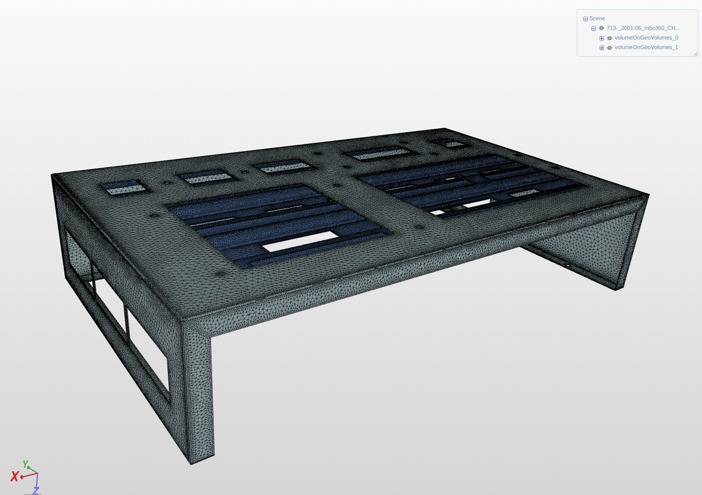
The overlapping face is now deleted and the red highlighted face is the only remaining face which is well connected to the larger non highlighted face. Considering this geometry, I tried to make a mesh and it succeeded. Figure below shows the outcome.
I hope this will help most of our users. If you have any question/s, feel free to ask.
-Ahmed (@ahmedhussain18)