Dale, just FYI, I am pulling the results and will do the paraview delta plot to see where the differences lie so we can get a real idea of whats happening 
I should have realized that, but what may be a reason the % inflation goes down with decreased # of volumes too?
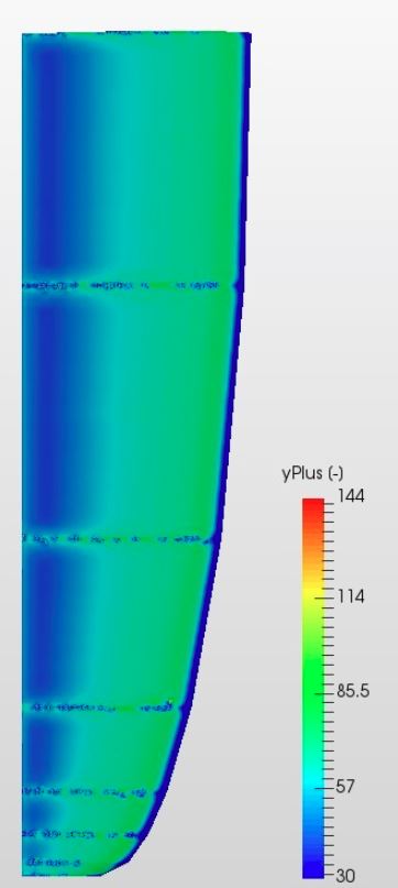
Anyway, yes the Y+ is still as good or BETTER at 82% as compared to 97% and larger cells. Here is Y+ map for bottom of wing (top was even better) for the Mesh4-1,837,511v mesh (YOU HAVE TO CLICK IT TO SEE FULL IMAGE):
Before I make a couple more smaller meshes and simulations, what about doing a full resolution mesh/run to see where we might end up? (quick map of how to do that if yes thanks…)
Dale
WOW, thanks, I haven’t learned ParaView yet as it won’t run on my Win7 machine ![]()
Good idea, let’s see if any result changes there, just pick your coarsest mesh and on the boundary condition for the wing, just change from wall function to full resolution and make a new run.
Best,
Darren
oh really? that’s a shame. Is it not supported or just doesn’t seem to work? If the latter, I might be able to assist.
Best,
Darren
It has something to do with OpenGL and drivers, I can load the file but get bunch of errors in log and no results on screen, tried to Google down the error but didn’t have much luck and had to move on to other things.
Output error messages started like this:
ERROR: In C:\bbd\7cc78367\build\superbuild\paraview\src\VTK\
Rendering\OpenGL2\vtkWin32OpenGLRenderWindow.cxx, line 733
vtkWin32OpenGLRenderWindow (00000000079A7680):

We have determined that your graphics system is an Intel
SandyBridge based system. These systems only partially support
 VTK. If you encounter any issues please make sure your graphics
 drivers from Intel are up to date.

ERROR: In C:\bbd\7cc78367\build\superbuild\paraview\src\VTK\
Rendering\OpenGL2\vtkOpenGLRenderWindow.cxx, line 781
vtkGenericOpenGLRenderWindow (000000000C08F750): GLEW could not
be initialized.
And went on forever until this last one:
vtkOpenGLRenderTimer::Stop called before vtkOpenGLRenderTimer::Start. Ignoring.

versionFunctions: Not supported on OpenGL ES
Any ideas, I was going to figure out how to make sure drivers up to date next but just got discouraged…

@DaleKramer, just to let you know that I shared a project with you, the results for layer inflation seem more robust (the inflation goes beyond the local cell size regardless. I am not gonna pretend I know what all the settings I changed do, but the combination seemed to work.
Still checking paraview (I forgot how to do it  )
)
WOW, I am liking those 7 changes, you got my 82% inflated to 97.2%. I’ll be using those again. Watchout though, some of them even make sense to me 
Thanks, I am waiting for full res to finish, went gangbusters to 432 sec and has been there for hour or so… BUT wait, it just stopped with error, nothing in solver log 
I still haven’t figured out a way to see core hours right after a job, takes a day or two to show up in ‘Usage Overview’
How to proceed?
Arg, just re-start it. I’ll investigate in the meantime
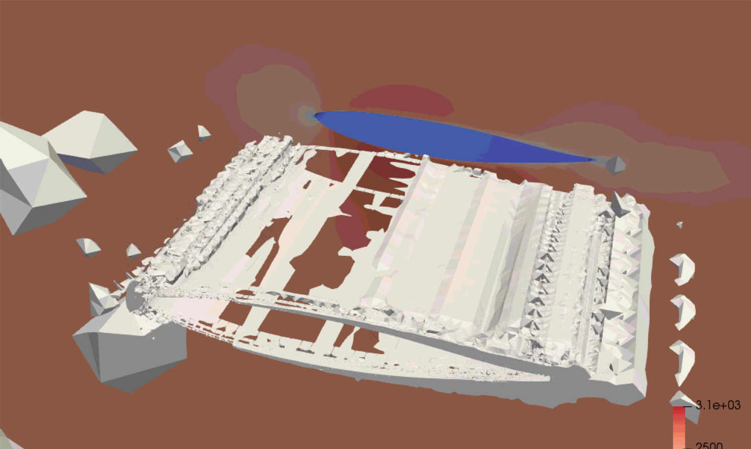
So this shows an isovolume of error, some interpolation error is present (big blobs in front of foil) but the main concern is the error along the upper and lower trailing half of the foil and the free shear behind the foil.
So what it means. The boundary layer at the rear altered, why? it should not have done if the layers were unaffected by the alteration in the number of cells, let’s see if this is mitigated with new robust cell inflating.
The free shear layer at trailing edge needs further refinement as that is the largest part of the error, although this is also likely to be affected by the boundary layer.
Let’s try placing a volume primitive (probably cartesian box) around that trailing edge and sufficiently behind into the shear layer and just give it a moderate refinement to see if any improvement.
Best,
Darren
P.s. the error was done between 1.8million cell mesh and the 1 million cell mesh.
I’ve started putting a Cartesian box at about 1/2 boundary box x,y,z dimensions centered around my geometry lately at Level 2, is that OK? It would help with the front blobs too?
I just watched the second Full Res runs Solver Log get to 1000s sec in 22 minutes real time with this output:
Time = 1000
DILUPBiCG:  Solving for Ux, Initial residual = 3.30136265817e-07, Final residual = 3.30136265817e-07, No Iterations 0
DILUPBiCG:  Solving for Uy, Initial residual = 7.22632225332e-07, Final residual = 7.22632225332e-07, No Iterations 0
DILUPBiCG:  Solving for Uz, Initial residual = 2.76239538071e-06, Final residual = 2.76239538071e-06, No Iterations 0
GAMG:  Solving for p, Initial residual = 0.00010139878738, Final residual = 8.77590431581e-07, No Iterations 8
time step continuity errors : sum local = 2.02242675354e-07, global = -3.16328409124e-09, cumulative = -7.4099086133e-06
DILUPBiCG:  Solving for omega, Initial residual = 8.94648323775e-06, Final residual = 8.94648323775e-06, No Iterations 0
DILUPBiCG:  Solving for k, Initial residual = 9.45154877351e-06, Final residual = 9.45154877351e-06, No Iterations 0
ExecutionTime = 869.66 s  ClockTime = 997 s
forces forces10 output:
sum of forces:
    pressure : (10891.4151619 -1415.70378042 108843.176221)
    viscous  : (2366.93789221 -7.50880843165 21.6967387809)
    porous   : (0 0 0)
sum of moments:
    pressure : (-6118408.98162 -2315824.76281 575388.215041)
    viscous  : (-972.649435072 1819.95092877 144206.14619)
    porous   : (0 0 0)
forceCoeffs forceCoeffs11 output:
    Cm    = -0.149276167513
    Cd    = 0.0293126611444
    Cl    = 0.240687445763
    Cl(f) = -0.0289324446317
    Cl(r) = 0.269619890395
End
Finalising parallel run
Doesn’t that show 1e-6 convergence for all residuals, if so why did it get to 1000s?
It is still showing status as Computing and ‘finalising’ as above at 36 minutes… and at 41 minutes … and at 45 minutes … and 50 minutes … and at 66 minutes … and finally at 82 minutes ERROR Runtime Exceeded
This is 2nd run of simulation ‘0aoa FULL RES - ABS Layered Mesh 4-431,533v’, 1st run errored.
Ok @DaleKramer I am copying the project to see if it runs for me. Sorry about this.
No, so convergence is if the initial residuals are below 1e-5 (or whatever setting) not the final one.
DARN ‘p’
I see that a lot stuck at 0.0001…
Yep, its a pressure based solver so it is normally last to converge. But it doesn’t mean to say that is not converged if the results are steady and continuity good, we can say its converged.
Yep, I’ve seen stable values as low as 100s so I assumed that they were good.
Good to know that it is OK to assume that…
I have fired off some simulation on the project I just shared with you, one looks ok the others look stuck also. I am logging off but will update you as soon as I am back on. Again, apologies.
Are you kidding, thank-you? I know how you spent your Monday evening 
Well things really started going well after you left.
I got rid of everything but the Geometry in the project and I created 4 versions on my new Mesh 1 that has been tweaked with your 7 parameter suggestions:
- Change the ‘Max face aspect ratio for layers’ from 0.5 to 2
- Change the ‘Max ratio of layer thickness to medial length’ from 0.3 to 0.9
- Change the ‘Min face weight’ from 0.02 to 0.002
- Change the ‘Min volume ratio between neighbouring cells’ from 0.01 to 0.001
- Set the Inflation parameter for 2 layers instead of 3 while maintaining the same overall sum of all layers thickness using the same expansion ratio of 1.1.
- This changed ‘Thickness of the Final Layer’ from 0.03821 to 0.06
- Decrease the ‘Minimum overall layer thickness’ from 0.02 to 0.0002
I adjusted the Background Mesh Box dimensions slightly.
I added a Mid-Volume Cartesian box to refine an area outside the wing to Level 2 (to help with the isovolume errors that were found).
I used the same Whole Wing Region box to refine the wing to Level 5 as before.
I then used a further 'All Surfaces refinement ’ to Level 8 instead of the Feature Refinement I used initially (this got rid of the refinements at each wing rib.
I then ran simulations on all 4 versions of Mesh 1 and a further Full Resolution Simulation on ‘Mesh 1-1,239,387v 32x16x16’
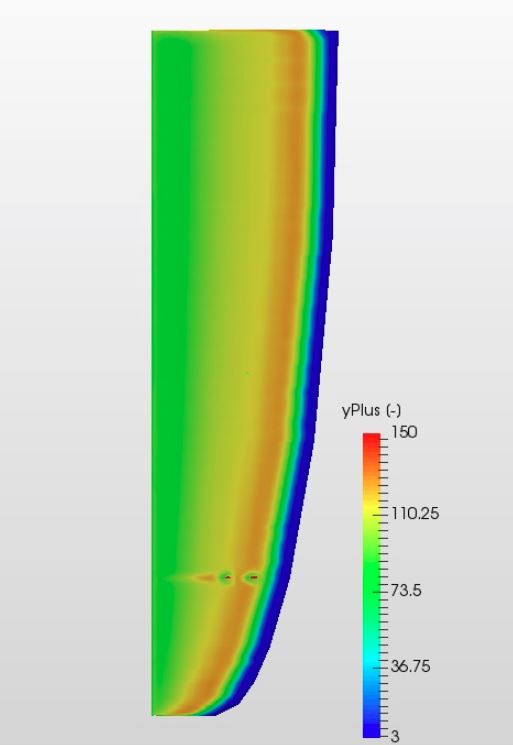
I looked at yPlus range on simulation ‘0aoa Mesh 1-1,239,387v 32x16x16’ and it looks pretty good I think (would like comment on this please, seems a little low on leading edge):
So then I just put the results in this new chart:
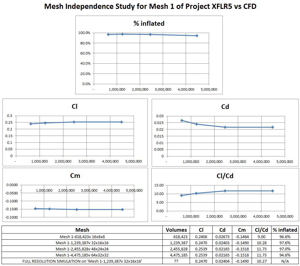
Darren, which mesh would you say to use for the definitive CFD results, the converged values or Full Resolution values?
Also, could you do your Paraview isovolume error check on the results?
I will put this data into a final XFLR5 vs CFD comparison chart once we are happy.
Anything else I should do except have a beer now ![]()
![]()
Thanks
Dale
P.S. Now after all that trouble, is there a way to make images that show where the boundary layer precisely separates at this 0aoa and 135mph case (not just particle tracing, maybe like a separation line)?
Hi @DaleKramer, sorry for such a late reply. In short, lovely results!
From these results, meshes of around 2.5 million do not significantly differ from that of 4.5 million, and there for the mesh independent results can be obtained from either but the cheapest would be the 2.5 million cell mesh.
On the topic of full res vs wall function, I looked at the results and saw that there was no significant difference between the two (correct?) and therefor doesn’t matter, for simplicity, stick with wall function. To be thorough, you could run a full res simulation with a mesh which has a y plus of around 1 all over, in theory, this should also be identical in results since it would be proving that the modeling of the boundary layer is a correct assumption but don’t think there is any point making extra work for ourselves.
Sure, I’ll download the results now.
Hmmm, not sure, can you maybe upload an image of what you mean from google maybe? Then I could say for sure. Does the BL separate at this 0AoA?
Best,
Darren