Would like to specify prism Growth Ratio AND first cell height for accurate initial guess for BL capture

Hi, I am doing a CFD simulation of a F1 rear wing design I’ve quickly knocked up in NX. With this kind of simulation I’ve read it is very important to make sure your mesh accurately captures the boundary layer, especially when dealing with large pressure gradients and wanting to check for/where flow seperation occurs.

Since I’m using SST turbulence model, I know I want to be aiming for y+ value of around 1. And from other reading, ideally I would want at least 25-30 prism layers, however, max SimScale will let me use is 20. In order to get a good first mesh guess, I’m following this video in order to calculate an appropriate Growth Ratio and rough intial total prism layer thickness estimate to completely capture the boundary layer.

Now, after using the CFD Online y+ calculator, and doing some rough code in MATLAB, I intend for my initial mesh to have the following parameters for the two aerofoil surfaces (main plane and flap):

Number of Prism layers - 20
Inflation BL Growth Ratio - 1.308
First Cell height - 1e^-5 m (based on Y+ calculator giving centroid height of 5e^-6m)
d99 - 0.007 m (initial guess of boundary layer thickness for at least the laminar part that I want the total prism thickness to cover)

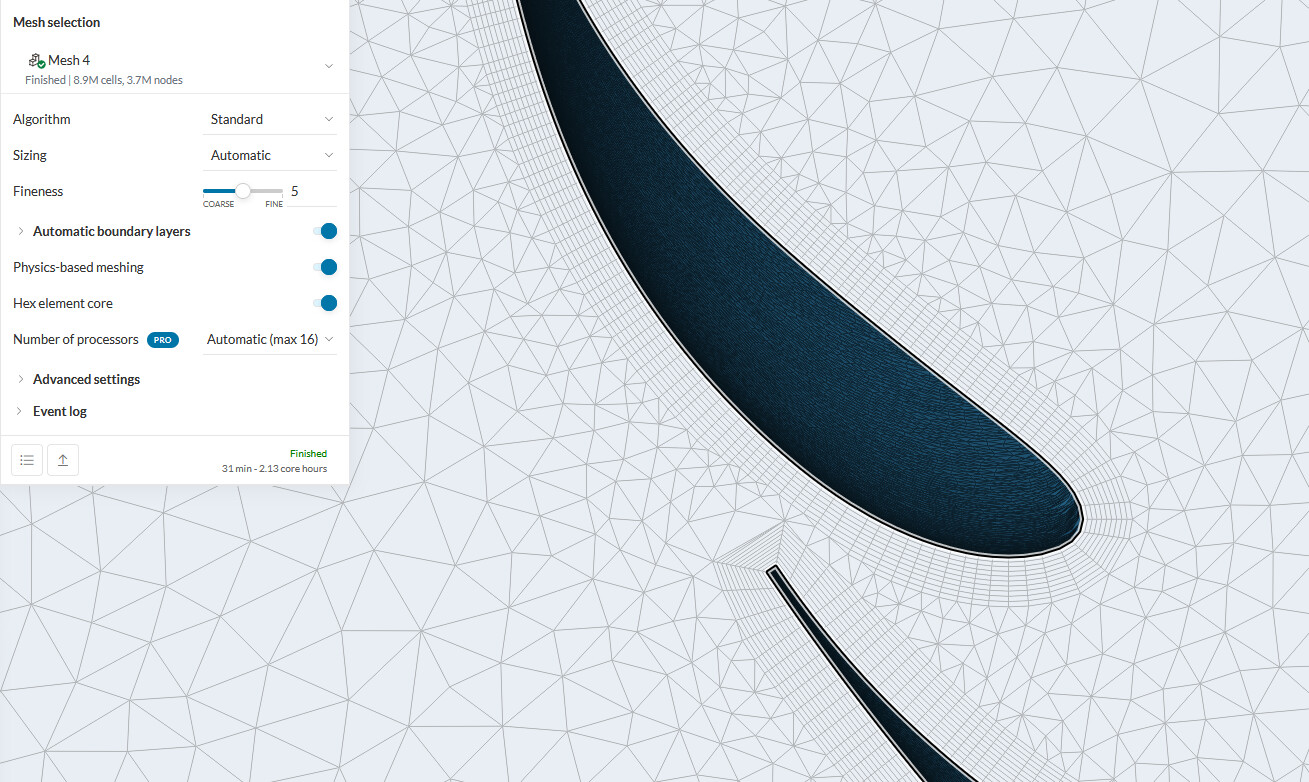
However, when I’ve created the inflate boundary layer refinement and assigned it to the main plane and flap, the automatic mesher only lets me choose between specifying growth ratio OR first cell height, I can’t choose both, and instead have to choose a ratio of the total thickness relative to the local mesh size.

To make sure the mesh’s prism layer total thickness is close to or equal to my calculated d99 value, do I need to take a rough guess of of local cell thickness from my initial mesh, then divide that by my d99 value to then get the required relative thickness ratio I need to make my prism total thickness close to the d99 value based on the first cell height I specify?

Obviously I know that these are all just rough strong first guesses, then with this first mesh that hopefully does an okay job at capturing the boundary layer, I can run an initial simulation, and from there I can better measure actual wall shear stress velocities on the aerofoil based on the pressure gradients the aerofoil profiles are giving me, and then chuck those values into MATLAB to reiterate and hopefully get a better boundary thickness guess to then recalculate prism layer thickness and growth ratios again.

Here is the project, the mesh I’m looking to create from this info is ‘20 PL with first GR iteration’.

Edit: So I just tried to generate a mesh with 20 prism layers on the aerofoils, with the default ‘Overall relative thickness’ of 0.4 and setting the first layer height to 1e^-5, and for some reason the completed mesh is just showing two prism layers, and zoomed in a lot to make sure it wasn’t just the first 18 layers being absolutely tiny compared to the last outer 2. Going to try again this time specifying the growth ratio of 1.308 instead.

Hello @shutchinson ,

Your thought process looks correct. Naturally, the question is what is the cell size on the surface going to be, so that you can configure the layers accordingly.

For a precise y+ definition, you should apply local element size refinements to the surfaces where layers will be inflated. This way you will obtain a better control over the mesh.

The “Overall relative thickness” is the ratio between the sum of the thickness of all layers, and the size of the cells on the surface.

For example, if you had a first layer thickness of 1e-5 meters with a growth rate of 1.3, the thickness of the final layer would be 1.46e-3 meters, and the sum of the thickness of all layers would be 6.3e-3 meters.

If you had a local element size refinement of 3.15e-3 meters, the “Overall relative thickness” would be 6.3e-3/3.15e-3 = 2.

Cheers

1 Like

Hi @RicardoParis thanks for your reply.

So I’ve finished generating a mesh, ‘Mesh 4’ in the project, specifying first layer thickness of 1e-5m and a 2.5 growth ratio since the smallest local refinement is on the flap at 2.5e-3, however I’m now running into the issue of my prism layers seem to be all at a constant thickness, and there are only 13 layers instead of 20. Should I be changing the values in the’ automatic boundary layers’ section? I assume not as that will also affect prism layers at the inlet, outlet and walls where 20 prism layers 6mm thick for each would be unnecessary.

Hey! At the moment, you are suppressing features (and cells in the aftermath) smaller than 5e-4 meters:

So the thin layers are getting suppressed. You can try decreasing the suppression to a value smaller than the thicknesses that you are looking for.

Cheers

Hi @RicardoParis sorry to bother you for one last time, so I decided to open a new version of this project with a slightly cleaner CAD model (noticed I didn’t create the gurney flap in the cleanest of ways).

Apart from that, the model is the same and same flow conditions, Re number etc, same mesh parameters etc. However I noticed in the mesh log at the beginning of the meshing process (top of the log), there was a line saying ‘Layer refinement was not applied on 1 faces because they were destroyed during the non-manifold boolean for conformal meshing or assigned as start/end faces in a sweep mesh refimenent.’

However, the mesh did manage to complete successfuly and didn’t spit out any warnings or quality issues, and I can’t see any missing faces on the mesh, I take it I shouldn’t worry too much about this?

It’s Mesh 1 in this new project.

This is likely a tiny surface that was removed from the resulting mesh for some reason (e.g. it was potentially suppressed with the small feature suppression, or some other mesh quality-related reason).

If the mesh looks Ok from your inspection, then it should be Ok.

Hi sir please i have a question for the overall relative thickness , is it very important to use the correct value? because there is a difference between what it said here and the formula SAE tutorial guide

I guess that it depends on how careful you would like to be with your mesh. If you can calculate what a “more adequate” value for the overall relative thickness would be to achieve a certain y+ value of interest, then I don’t see a reason not to do it :smile:

ok thank you sir