Wind Log Function as Velocity input & Meshing of an Urban Environment

Hi Barry,

So I looked at that project and indeed he used X, Y and Z however he did define also the velocity components in the X, Y, Z which I don’t know why this was needed (I personally would have tried to just use the verical ordinate but maybe there was a reason). this still means that you are not defining the velocity components here his his graph:

VelVary1

And here is yours:
VelVary2

So your Column index 4 is missing the other two components of the vector.

so for this line with velocity only in the x and using the template you are following:
0.0, -482.5, 0.515661589, 0.256048522, 0 ,0 (6 columns)

Kind regards,
Darren

Hi Darren,

I followed up on your suggestion and attempted to run with the adjusted csv files but it ran into an error again, this time stating “Inconsistent boundary condition types. Possibly the empty boundary conditions were not correctly assigned for a 2D mesh. Please check the boundary conditions.”

You can refer to it in more detail on “Steady State Mesh 2 Coarse” > “ABL 1”.

Let me know what you think.

Cheers,
Barry

Cheers Barry,

I’ll do a bit of experimenting and get back to you.

All the best,
Darren

1 Like

Hi Barry, I am unable to run anything atm but here are a few things I found starting with a visualisation of your data for inlet:


Notice the last line of points there were some missing I corrected to look like this:

And also you have an upload for k and omega, they should be scalar which is one value, not a vector which is 3 as defined in your uploads, any chance you could make these alterations and see how it goes?

Many thanks,
Darren

1 Like

Hi Darren,

Ah yes I double checked and there seems to be a missing set of values. Will adjust as needed. Thanks Darren!

About the k and omega, according to the Greenmark document in the first post, k should be a scalar and omega changing as Z changes. I posted them below for your reference. Am I reading this incorrectly?

Capture

Will attempt to re-run with the adjusted values.

Cheers,
Barry

Hi Barry,

Sorry, to be clear I am refering to the format of the CSV:
kCSV

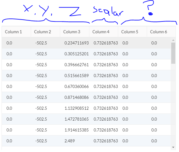
There are an additional 2 columns?

I checked the example and it only had 4 columns for k and omega

Hope this helps,
Darren

Hi Darren,

Sorry I didn’t make it clear. I have not adjusted the csv file at the moment and will add the additional two columns later plus do a run when I have time.

Thanks for the help Darren!

P.S Great drawing on the columns :wink:

Regards,
Barry

2 Likes

lol cheers :smiley: A* art student :wink:

Hi Darren,

If you refer to the [project][Deleted by author] “Steady State Mesh 2 Coarse” > “ABL1” the values have been adjusted with the additional columns and again an error.

Regards,
Barry

Hi Barry,

I think the velocity upload is ok but you haven’t removed the two additional columns for k and omega file uploads?

Cheers,
Darren

Hi Darren,

Apologies I thought you meant add in the columns :stuck_out_tongue:

I’ve removed them and still same issue and error. You can refer to “ABL 2”.

In the meantime, I think I will get my partner to re-mesh and run it. Maybe that might help. Let you know if it does work out.

Regards,
Barry

Damn, ok is there any chance you could email me the CSV’s? I’ll pm my address.

for k the value in the 4th column is constant, is this deliberate?

If you made a really coarse mesh for testing the setup that would save a lot of time. So the error is the boundary condition apparently which makes me suspect the CSV’s, or the setup, once they are ruled out then we will need someone to investigate it.

Kind regards,
Darren

Hi Darren,

I could just link you my dropbox link where you can download it.

Well I need to confirm the K value but referring back to my reply where there is a figure of the equations, so far K is constant. You can refer to the Greenmark document page 101 for a more detailed look.

Sure we are working on that now. Will update you if there is any progress. My suspicion still stands on the meshing issues, but we’ll see after we’ve meshed out and tried again.

Cheers for the help!

Regards,
Barry

Hi Barry I just removed all CSV’s and the error was still present. So I will now go and check your boundary conditions. Did you get a coarse mesh produced?

Cheers,
Darren

Hi Darren,

Was just about to post here. We managed to get not only the simulation starting, but also produce a result. It seems like my initial guess of the mesh being distorted at the bounding box was the issue. However upon downloading the results earlier today, it seems like the velocity gradient you expect from the function much similar to Vaibhav’s simulation is completely not present. Very strange result indeed.

Here is the link to the [Project][Deleted by author]. You will find that there is a new mesh similar to what we have been working on with the exception of the bounding box being larger as I discovered that at a certain distance, the surface refinement for the surrounding geometries was distorting the bounding box mesh. So I just simply increased the size of the box in all directions except Z by 140m. This mesh is named “Surrounding 2 Mesh 1 Coarse”. The simulation run is called “Steady State Mesh 2 Coarse” and the run is “ABL Run 1”.

Also of note is that ABL 1 is before you corrected me on removal of the final two columns under the K and epsilon for the inlet boundary condition. Since then, we’ve done the corrections and that run is at the same location but “ABL Run 2”. It just finished running an hour ago and I have yet to check or download it.

Do let me know if you need anything else. I will continue to converse with my partner to see what else we can do to get the desired outcome.

Oh I almost forgot to mention. I again suspect the mesh is the issue as when I opened “ABL 1” into ParaView and loaded up the “Surface With Wireframe” view there are several distortions in the mesh at the YZ plane at Zmin and Xmin as you see below. I suspect that may be causing the lack of a velocity gradient, but its very surprising it still can run. So I’m rather perplexed at this point.

Regards,
Barry

Excellent, glad that hurdle has been passed! I will look into you velocity gradient now.

Kind regards,
Darren

Thanks Darren. For your better understanding, I’ve attached two sets of photos. The first set is our simulation run and mesh where we expect the velocity gradient. The second being Vaibhav’s velocity gradient and mesh which is very clear. Hope it helps!

Set 1

Set 2

Cheers,
Barry

1 Like

Hi Barry,

How are you determining convergence?

I noticed in your simulation setup you are running 800s with iterations 10s long, this means you have done only 80 iterations. Simulations rarely converge in that time, especially with large simulations with fine details (such as this one).

Looking at your residuals plot:

For a converged simulation I would expect all residuals to be below 1e-4 and for some form of monitor to prove that a steady state has been reached.


These slices show as 600s (60 iterations) and 800s (80 iterations) and there is visually a lot of difference. I have adjusted the simulation setting and added result controls for forces on a building at the inlet, outlet and just behind your building of interests. In terms of your ABL, it looks correct at the inlet and for it to be present in the rest of the solution you need to give it time to develop (more iterations).

Also in these slices show the scale in meters, I zoomed in and compared the ABL at the inlet with the CSV and they seem to marry up. i.e. the free stream being approximately 1.8m/s at approximately 7m vertically.

The altered project is here, it just needs running:

Hope this helps,
Darren

2 Likes

Hi Darren,

Thanks for the help. Looks like you did a lot of work! Thank you!

Well you did kind of stumble upon my future question in that I wanted to ask about convergence the what exactly do the individual parameters in the convergence graph mean plus timestep.

For convergence my limited knowledge is just to look for a downward trend for a rather developed simulation time which indicates stability. I’m not exactly sure what numerical parameters to look out for when determining a good convergence. With that being said, I was skeptical about increasing the timestep but doing seemed to reduce the likelihood the simulation would fail at 100% because of either unknown reasons or something along the lines not enough storage. Not sure exactly why this happens. On the other hand what would be an optimal timestep? I remember your comments on timestep not being such a large factor when it comes to steady-state flow but it seems like in this case it does matter?

As for currently resolving the ABL issue, understood. I will allow the simulation to develop but as I previously asked, what will be a good way to gauge the time needed? So far my basic calculations just account the time needed as the distance required to be covered by the flow. Example for a 2m/s flow to cover 1km it will need at least 500s.

Speaking of 2m/s, that is the ideal absolute velocity that I’m aiming for. Seems like I need re-adjust the ABL to meet that. Again, thanks for the help Darren. Looking forward to your reply.

Regards,
Barry

Hi Barry,

So a downward trend doesn’t really indicate stability, it the reduction in error. I could read a lot of information here but I don’t think that is necessary. Here is a good article:

But for this purpose, we need to really look at solution instability within the solution (the monitors I added) most solutions are likely to be converged when all residuals reach 1e-6 but this can vary dramatically either way.

This calculation doesn’t work for steady-state problems, time is an iterator in SimScale, not a physical quantity (it would actually make more sense if it said number of iterations instead of time and step length)

This is likely due to amount of time steps written (at the moment you are set to every 100), in steady state you are only really interested in the final timestep and maybe 1 or 2 in between to see solution development if you are interested so this could be reduced drastically and should remove any notification of out of memory or warnings about number of steps written.

Hope this helps,
Darren

1 Like