As per standard procedure, here is the project [link][Deleted by author].
This is less of a project issue as of more a mix of getting things correct.
So some background, this project is two fold, to deduce the average wind velocity on a specific floor in the building of interest and to also deduce the Turbulent Kinetic Energy just outside the interested region of the building of interest. With reference to the Greenmark reference document for ideal simulation characteristics, specific requirements for a “proper” result are given.
While I’ve kind of figured out a large part of the things I need to do (thanks everyone who helped along the way), input of the wind log function (page 101 of the document) and the meshing characteristics I want are still issues.
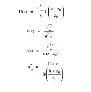
The wind log function or rather the inbound vertical wind profile is described here but a simplified version that I want to use is stated in page 101 of the reference document. The question is how do i input such a profile? On top of this, if my desired absolute velocity is 2, again how do I input this value into the boundary conditions?
Second problem, so far I’m aware that in order to allow for some sort of ground effects to be included into the simulation, I’ve referenced the validation case for “Wind loads on buildings” in the Simscale Validation documentation. There they have two important sets of mesh refinement I’m unfamiliar with. One the bounding box layer refinement to produce a fine mesh from the bottom which gradually increases in size as height increases. Two, the inflation of the boundary layer. How do I use those meshing refinements optimally and in particular, is there a way to calculate out the values to input into the parameters of both meshing refinements?
Additionally, if you are interested in the geometry I’m trying to mesh, refer to “Full Geometry 1”.
Thanks for the help! I hope you don’t mind the long read!
great stuff you’re working on there - excited to see the results!
I’m currently in a hurry, so I’ll post more shortly. But as a first hint: @anon5245009 demonstrated the use of atmospheric boundary layers over in this project: [Deleted by author]. The table upload for all quantities allows you to specify arbitrary profiles as BCs. We’re also working on making this easier.
Regarding the second question you can say that the Box Layer refinement is similar to the Layer refinement but only for the bounding box which is particularly useful for external flow analysis where the box surface acts as a wall for the flow domain and must be refined with a layer mesh for accuracy. The additional parameter you have to choose is the box face for layer generation.
Let us know if you need any further help and do not hesitate to ask. We are happy to help!
Thanks for the input! I will try it out and see if I am able to obtain the desired results.
About the Box Layer refinement, I’m aware of roughly how it works and what it is used for but is there a suitable way to calculate and a determine the optimal parameters for different sizes of bounding boxes or what kind of flow analysis is being planned. I’ve played around with the values but just cant seem to get a fine enough refinement. Same issues as well for the inflation of the boundary layer, no idea what is the optimal way to use and calculate out the values to be input for optimal result.
Hi Barry, The parameters are more down to fluid and flow parameters than bounding box size. If you know how thick your layers need to be from a Y+ calculation it is best to use absolute values. What issues are you facing are they not inflating with your desired values? For absolute values, this can be a bit tricky.
If you want to provide the thicknesses etc that you need I could try meshing it for you and give feedback on what I did?
Thanks for the input. Great info on parameters. So far I’ve only tried once and the bounding box layer addition is working just trying understand and figure out what the optimal values are. Regarding the inflation of the bounding layer I have not attempted that yet and will do so shortly.
You are very welcome to try to mesh. If you need guidelines for grid size of the mesh they are in the Greenmark document page 100 under Grid Size. The building of interest is in the center, refer to earlier geometries and you can see which one it is.
Hi Barry, Just want to get clarification on what you mean by ‘optimal values’, I think maybe it’s best if I explain what the parameters mean?
if so here is a brief explanation:
the number of layers = n: the number of layers you want to inflate, if you have very large cells at the boundary but the desired y value is very small in comparison then you might want to inflate slowly over many layers.
Expansion ratio = R: the rate in which the layer will increase, for example, if the first layer is 1mm thick the second will be 1.3mm and so on and so forth.
The thickness of final layer = Y_final: the thickness of the last inflated layer, this will be Y_first*R^n = Y_final. Y_first being based upon the desired 1st y+ distance, if modelling as a wall function this will be 30<Y+<200 and there is a calculator on CFD online to calculate y based on Y+.
[-] or [m] is weather or not relative or absolute values are being used in the main mesh settings (use absolute if you need a particular distance)
And for the bounding box layer addition, you need to choose which face you will be inflating.
So there isn’t really an optimal set up of such, it really does depend upon your case, the flow and many other things.
Let me know if you need more info on anything in particular?
As usual this is the project [link][Deleted by author], the mesh that I’m about to refer to is “Surrounding 2 Mesh 1 Coarse”.
So I’ve had a fellow student mesh out the needed geometry after we deliberated on the parameters we require. Seems like we’re almost there. However our problem is that the .csv file that we calculated out to be the velocity input that mimics the atmospheric boundary layer profile just gives an instant error when simulating. We suspect it has more to do with the bounding box layer addition. While I think we got the numbers correct and the .csv file fits well with the values we calculated, the mesh as you can see at the Xmin-Z plane (bounding box 3) near the Zmin does not have a very uniform mesh. We tried increasing to bounding box length to compensate for this but it still gets distorted and now we don’t really have any ideas on how fix that.
Thanks everyone so far and hope to get this resolved soon!
Hi Barry, was it a fatal IO error? It might be the CSV format, can you create a simulation with the CSV and produce the error so I can see? We can go back and polish the mesh if it is indeed the fault.
Hi Barry, so the CSV format is a bit different to what you have specified here is a bit of an explaination.
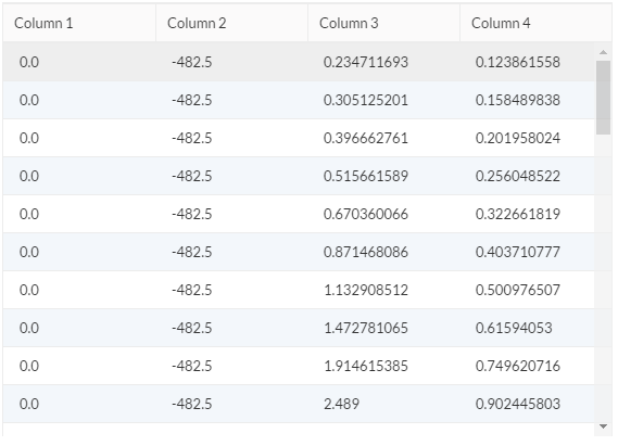
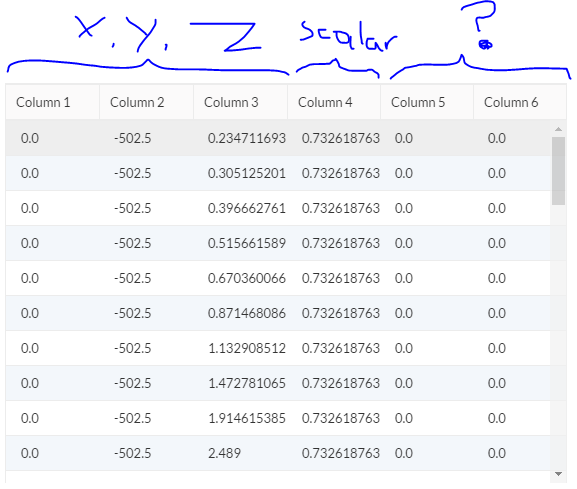
you have selected variables in the x, y and z. Intuitively this would be the components as you have defined, however this isn’t actually what they signify. x, y and z signify the position at which you are deafining a value for (the value being in vector form) so what you have actually done is given it alot of coordinates without a value/vector. what you need to do in this instance is select Y component and lay out your CSV like this:
Y ordinate, X velocity,Y velocity, Z velocity
0, 0, 0, 0
The first being zero velocity signifying the velocity at the wall.
Let me know if you have more questions on this,
Darren
Apologies but while I understand what you mean by a wrong selection and needing to select the Y component, I’m still very confused about how to actually set up the CSV file properly.
I took reference from [Vaibhav_s ABL Simulation][Deleted by author] and it seemed like his first column defines the coordinate position in X-axis from X-min, second column defines the direction in the Y-axis from Ymin, third the Z axis from Zmin and fourth the velocity profiles for each layer in Zmin.
So I looked at that project and indeed he used X, Y and Z however he did define also the velocity components in the X, Y, Z which I don’t know why this was needed (I personally would have tried to just use the verical ordinate but maybe there was a reason). this still means that you are not defining the velocity components here his his graph:
I followed up on your suggestion and attempted to run with the adjusted csv files but it ran into an error again, this time stating “Inconsistent boundary condition types. Possibly the empty boundary conditions were not correctly assigned for a 2D mesh. Please check the boundary conditions.”
You can refer to it in more detail on “Steady State Mesh 2 Coarse” > “ABL 1”.
And also you have an upload for k and omega, they should be scalar which is one value, not a vector which is 3 as defined in your uploads, any chance you could make these alterations and see how it goes?
Ah yes I double checked and there seems to be a missing set of values. Will adjust as needed. Thanks Darren!
About the k and omega, according to the Greenmark document in the first post, k should be a scalar and omega changing as Z changes. I posted them below for your reference. Am I reading this incorrectly?