\underline{\textbf{Status}}
Not started yet.
\underline{\textbf{Description & Overview}}
Information: The CAD models will not be provided and have to be modeled!
Wind Load Calculation is an overview of the force that blowing wind exerts on a tall object. A number of factors that influence the actual wind load on a real building, include the surrounding terrain, nearby structures, trees, and typical weather patterns for the area. Comparing wind load calculations are most complicated . Calculations try to account for as many of these external factors as possible, to the point where the wind load section in American Society for Civil Engineer’s ASCE 7 standard, spans five chapters and over 100 pages.
\underline{\textbf{Input Data}}
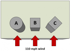
Fig.1 Wind load calculation example structures
- A 10’ tall, 10’ wide cylinder.
- A cube with the same volume as cylinder A, oriented with a face normal (90°) to the wind direction.
- Another cube with the same volume, but rotated 45° for a slightly more aerodynamic front.
Wind load equations are also given (see sources):
F = wind load (in N or lbf)
P = wind pressure (in Pa or psf)
A = projected area (in m^2 or ft^2)
C_d = drag coefficient (unitless)
V = wind speed
K_z = exposure coefficient
G = gust response factor
z = height of the midpoint of the object above the ground
h = height of the top of the object above the ground
q_z = velocity pressure
G = gust effect factor (as defined in ASCE 7 §26.9)
C_f = force coefficient (as defined in ASCE 7 §29.5)
K_z = velocity pressure coefficient (as defined in ASCE 7 §29.3.1)
K_zt = topographic factor (as defined in ASCE 7 §26.8.2)
K_d = wind directionality factor (as defined in ASCE 7 §26.5)
\underline{\textbf{Purpose}}
The purpose of this project is to validate the results given in the pictures below and to use the formulas given in the sources. The calculation methods shown can offer a very accurate simulation of the ultimate wind load on a structure, but they do not offer a complete picture. They cannot indicate where wind load might be concentrated on a complex structure, nor simulate the resulting stresses and deflection of the structure. For a more complete understanding of how a structure will react to high wind loads, an engineer can use Computational Fluid Dynamics (CFD) and Finite Element Analysis (FEA) programs to simulate the interaction of the wind and structure as a whole.
\underline{\textbf{Pictures of some results}}
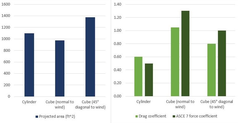
Fig.2 Wind load calculation factors for three different structures
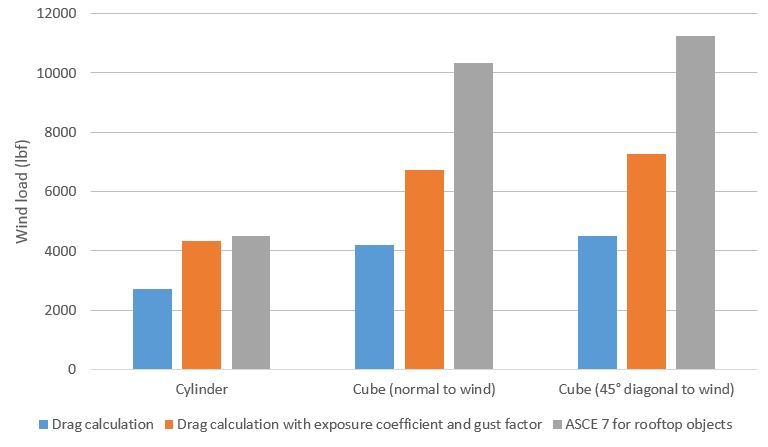
Fig.3 Three wind load calculation methods for three different structures
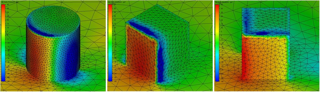
Fig.4 Static pressure on three different objects in a 110 mph wind
\underline{\textbf{Key Words}}
Computational fluid dynamics, CFD, Mathematical models, Wind Load, ASCE 7, Building Load, American Society of Civil Engineers (ASCE)
\underline{\textbf{Literature & Sources}}