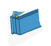
I’ve created a simple model in which I’ve connected a sensor (simplied by a large block) to two smaller blocks, which subsequently are connected to a plate by means of welds. See figure below. The assembly should be able to sustain an accelartion of 30g in the vertical (negative x) direction. Eventually, I’m interested in the maximum stress that occurs in the welds. See the link to my project at the end of this topic.
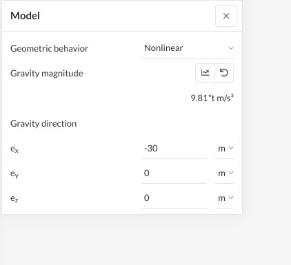
Initially, I’ve applied a 30g acceleration through the “Model” option (see Run1). As a check I’ve also applied a volume load to both the sensor and the two smaller blocks (see Run4). In contrast to what I expected I see a very large difference between the maxuimum stresses that occur between the two scenario’s (0.45MPa vs. 13.44MPa), while I would expect a more similar value.
Can someone maybe explain what the reason is for this large difference?
Applying 30g to the model would be similar to simulating weight load on all components (including plate), except 30 times larger than on Earth.
A better approach would be indeed to apply acceleration on the sensor and blocks.
Please note that there are potentials to greatly reduce simulation time here:
simply ignore the part “plate”, and use “fix” constrains at weld
Depending on the acceleration direction, feel free to halve the model and use “symmetry” constrain
Additionally it is always a good idea to have a rough “pen-and-paper” calculation to have a feeling of the magnitude of stresses to be expected.
The force should be: F=mxa,
where m=mass of sensor and blocks, a=30g
From there and with the cross section, the shear and bending stresses can be calculated which could be compared to the simulated value.
I see a difference in the models, in that you did not apply the volume load to all parts, which is done when using the gravity model. This breaks the equivalence.
On the other hand, I would like to know how you computed the volume load, could you please show me equations and calculations?
Unfortunately I still do not fully understand why there is such a large difference in de maximum stress peak between Run 1 and Run 4. If I compare the simulation setup between Run1 (where I apply 30g to the complete model, including the plate) and Run 4 (where I apply a volume force to only the sensor and two blocks) I would expect that the simulation setup is more or less similar. Reason for this is that despite the plate also experiences an acceleration of 30g in Run 1 it is completely fixed at the sides and cannot move. So in Run 1 I would expect that the stresses in the welds are only caused by the pulling force of the sensor and two blocks (which is similar to the situation in Run 2). Or do I make a mistake in my reasoning?
Concerning your comment about the fact I did not apply a volume load to all parts. You are indeed right, but I do not see yet why this should make a difference? See also my last question directed to Jani in my post of a few minutes ago. Can you maybe explain at which point I make a mistake in my reasoning?
To calculate the volume loads for each part I have:
Derived the mass and volume of the part;
Multiplied the mass by 9.81 and by 30 to arrive at the total load;
Divided the total load by the volume of the part to arrive at the volume load.
I can’t answer your question directly but I do have a few suggestions.
Have Simscale calculate the Reaction Forces at the at the edges of the plate. This will allow you to check the loads being applied for each load case and give you an easy way to compare them.
Use second order elements. You are applying a bending load to a thin part with only one element through its thickness. This is a common source of inaccuracies. Since each Run has different loading this will affect each load case differently.
Bonded contacts (in all programs) are inaccurate and you do not want them near high stress areas or areas that you are interested in. Run 4 very clearly shows you the discontinuous stresses around the weld. Since you are not using different weld properties for the weld I would merge all steel parts into one part. Another option would be to create two surfaces in the plate the size of the welds to try and force a compatible mesh in that area. This can be done in Simscale using the Imprint command.
I am not sure if the Gravity Direction can actually scale the gravity value. Maybe @ggiraldof can confirm this.
Well, I hope some of this helps out. Good Luck!
Christopher
I think mathematically it should work, but as I am not 100% sure, it should be tested. In any case, it doesn’t look to me like a good practice, I would always recommend to use a unitary vector here.