I am starting to use this simulator, i am very new to CFD and to SIMSCALE
I ve transfered a pond design from onshape, and looking how this simulator perform, the thing is for some reason, I get the following error:
“A multi-region mesh was assigned - this analysis-type requires a single-region mesh”.
(…)
I tried many configurations.
The project is here: https://www.simscale.com/workbench/?pid=9207996278568178168
My last Config. with a material mesh configuration, and the point inside the water volume, resulted in a request to use the mesh as domain, which happen to delete all the structure holding the lagoon and the inlet outlet pipes.
I would be grateful to be offer any advise. Feel free to ask any question.
I only want to check dead zones, and the flow profile, using 3 inlet pipes and 3 outlet pipes, at constant water level to start.
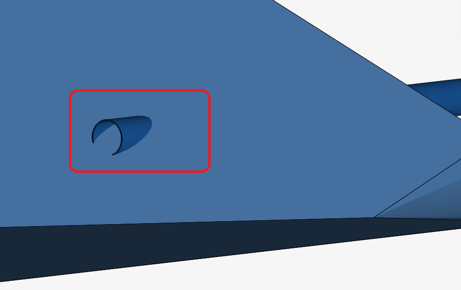
I am not quite satisfied with the geometry. The tubes simply penetrate the body you are working with which is not very clean. Additionally your faces are not closed - a watertight CAD model is vital!
So before talking about setup and physics in general I would make sure that the geometry is (almost) perfect to make sure we eliminate the biggest culprit in the process of simulation.
Yeah, its not the complete design, since it would lead to multiregion mesh, which I think wont work, on the simulation, yeah the pipes were made on a Rush, and not so clean. I dont really now Watertight CAD Models, But I will check it later, Thanks for the advice.
Ok, before anything sorry for my english, I need a lot more practice.
The thing is, that when I tried first time, I inserted everything from onshape, did not work because it was multi region, so i started cutting parts from a branch I did there. Now I am triying to make it work with just the solids that represent the water, with no walls, no pipes, maybe the mistake is that the pipe should be full solid, to work, I am still testing, the model you saw Jouse, If it does not work, I will make the pipe full.
After that, if It does not work, I will bring again the boundaries from onshape, but I am afraid that when making a mesh It will take it as multiregion, making it fail from beginning.
I ve tried with a different model from onshape.
And again this happen : Simulation assignment on the geometry is not supported for the currently selected mesh. Try to regenerate your mesh or use the mesh as simulation domain.
When I use the mesh as simulation domain, It ask to reset assigments, I do this, the thing is that mesh does not seem to represent the system I want. But I tried the run, selecting the mesh external walls as boundaries, and the mesh hole (where the pipes were) as inlet and outlet, and fixed the velocities that I calculated on the design, It did not let me use the fixed mean velocities, so after many tries and combinations Ive ended deleting the outlet configuration, and only was allowed to enter the flow in the entrance, (inlet) in order to make the run work., but again it failed.
Also configured the material as water.
Can you explain what you are trying to achieve in the simulation as it is not obvious. On your model it looks like a body of water with 3 pipes running through but of course you can not mesh solids with the incompressible solver (there is no need to) so in your mesh you get a single body of water.
There are also issues with your boundary conditions but we can get to that once we understand what you are trying to model and achieve.
Hello Roy. Thanks for reading and your time. The design is a full mixed aerobic lagoon. My idea is use CFD to see the direction and speed of water in the pond, to optimize it, and minimize dead areas, to decide the number and position of the aereators. Usually ( at least here) we use a random number where with a x = 6 ( L/B) we have 2/3 of effective volume. Since I am starting to draw in 3D with onshape, and had the chance to check CFD ( I am very new to both of this) I wanted to try. And get a 3D profile of the flux in the pond. The inlet are the pipes which are equal than the outlet since the pond works at constant water lvl (4m). And they should mantain a total Q of 0.44 m3/s or 1.27 m/s as lineal speed(y axis), I tried in my last attempt with onshape to add a cover to the water ( color black) and fill the pipes with a solid. Then in simscale I tried to check the solid inside the pond and the pipes as water, and the solids (cover and pipes) as boundaries. Obviously it was all erased after the first mesh error. Well hope this make some sense. Please feel free to ask anything you need. And thanks a lot for the attention and help.
If I am understanding your needs and if you are not interested in wind and wave action mixing, then just CAD one watertight solid of the water in the pond and the water inside the inlet and outlet pipes.
Treat it as an internal incompressible simulation. define inlet pipe faces with velocity BC and outlets as 0 pa gage pressure faces.
Make the surface of the water a slip wall and all others as no-slip walls with appropriate boundary layers.
@jousefm , @roy_g, @DaleKramer
Hey there, thanks to all for your answer, I am triying again, following all the advices =).
I did all DaleKramer told, just used the terrain as no slip wall, if its not working, I will delete everything from the cad on onshape but the water. I hope this time works.
Thanks again a lot, and please excuse my poor knowledge on this area.
The onshape CAD is here Onshape
Try #1
Tried one with Very Coarse option:
Get this error: Some interfaces could not be resolved with the applied mesh fineness. Please check the Meshing Log for more info. Will go on Coarse now.
Try#2. Redesigned only a water body, triying to make it watertight, Mesh it as Coarse, get this error now:
“Partial interfaces were detected that are not taken into account. Please check the Meshing Log for more info.”
During the run I get this:
“A multi-region mesh was assigned - this analysis-type requires a single-region mesh.”
Will recheck and try again, with only 1 part solid.
Try#3.
One part Solid Mesh : OK!
Running now, @DaleKramer Just one question, I would be grateful if you could explain me, why pressure outlet = 0. In the design, the ideal working condition, is a stacionary one, where the DQ = 0, the flow that enters = flow that exit, I dont really understand, why I can choose inlet and outlet as fixed flow value.
If the water is flowing into pipes that are inlet pipes, then that water has to come from somewhere else in the tank, I assumed that the pipes on one end were inlets and the ones on the other are outlets and that there was an external pump between the inlet and outlet pipes that are not shown.
The BC conditions that I use for my aerodynamics simulations are as I described. I believe they are what you should use.
I assume that you know the entrance velocity in the inlets and that is all that you know. If so, that is why you need the zero gradient outlets which will make sure that inlet flow rate equals outlet flow rate (I believe, but someone else following this with more experience in this area might suggest if there are better BC’s for you). I think that equal velocities on inlets and outlets does not work well if the total inlet area does not EXACTLY equal outlet areas and the zero gradient method handles minute differences in areas gracefully.