Dear SimScalers,
in this weeks spotlight we will have a look at a Finite-Element simulation of a Battery Frame by our user @ReCalculating.
For the whole project documentation, please have a look at his awesome blog: http://lopified.blogspot.de/
Introduction
The main purpose of the whole project is to convert a Volkswagen Golf into an electric vehicle.
Specifications of the car:
2003 VW Golf GL 2.0L
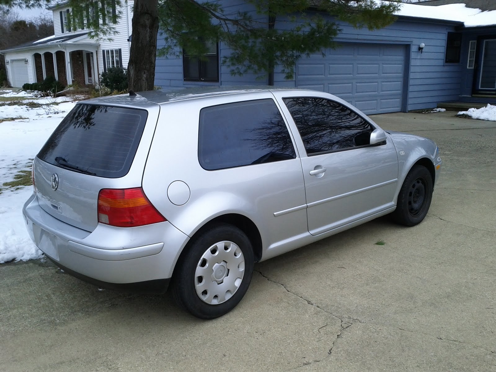
Courtesy: Knot Lopii (BLOG)
Gross weight: 3670lbs
Curb weight: 2771lbs
Weight split: 61%/39% F/R
Drag Coefficient: 0.31 Cd
Drive:
Engine: 2.0L ~130kg
**Torque:**122ft-lb @2600 rpm
Horsepower: 115 @5200 rpm
5 speed manual front wheel drive
Chassis:
- RR shock blown
- Exhaust header flex coupler has a hole
- RF hubcap missing
- Engine bay belly pan missing
- Headlights a little clouded
- A few dings and scratches
- Lower rear engine torsion mount loose
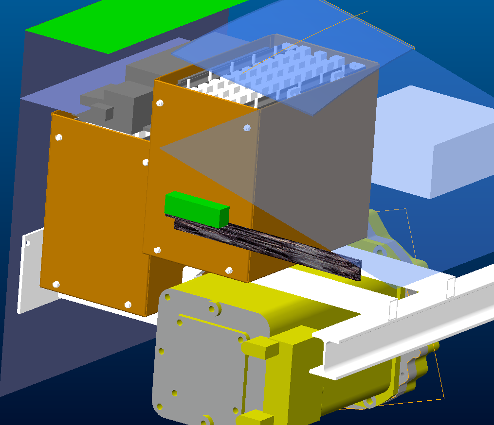
The battery frame simulated on the platform will be used to hold the front two battery boxes and a DMOC645 inverter.
@ReCalculating used SimScale’s Finite Element Analysis Module in order to determine and investigate the stress field as well as the displacement fields of the structure.
For this simulation different g-forces were used in vertical, lateral and longitudinal direction:
-
1g Vertical (Configuration 1)
-
3g Vertical, 2g Lateral, 1g Longitudinal (Configuration 2)
-
5g Vertical, 5g Lateral, 5g Longitudinal Stress Field (not in the project) (Configuration 3)
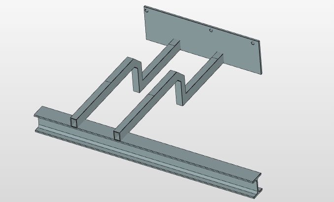
Geometry
Format: STEP
Meshing
Type: Tet-dominant
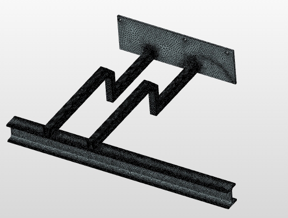
Mesh Information
-
Nodes: 77631
-
1D elements (edges): 13056
-
2D elements (faces): 135360
-
3D elements (volumes): 257179
-
Bounding box diagonal length [m]: 1.17898
-
Bounding box length in the x direction [m]: 0.9144
-
Bounding box length in the y direction [m]: 0.1727
-
Bounding box length in the z direction [m]: 0.7239
Simulation:
Type: Static Analysis - Advanced
Material: Steel
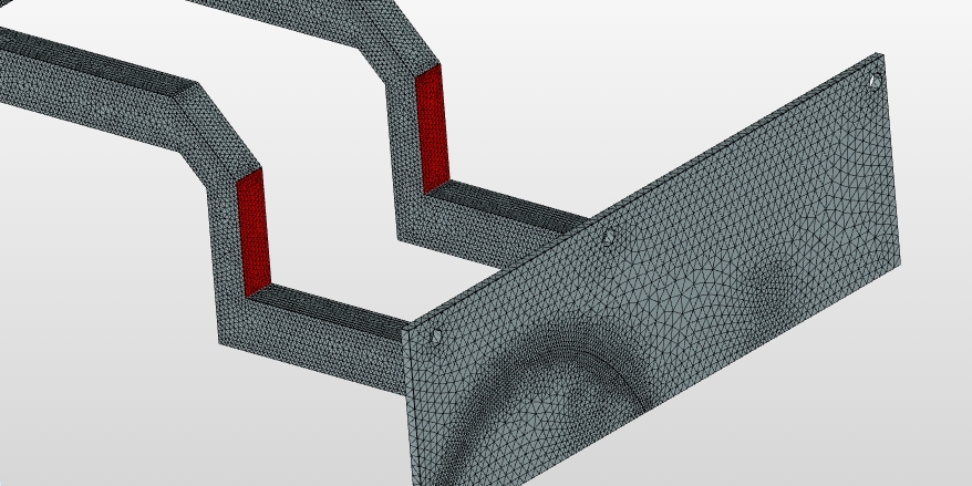
Boundary conditions
Fixed support has been used on the highlighted face (on both sides).
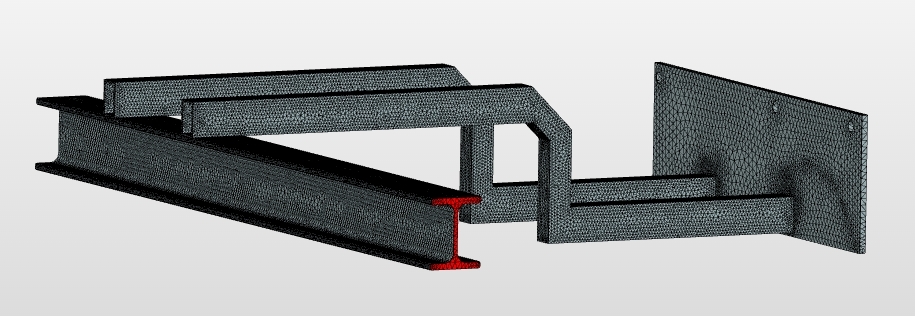
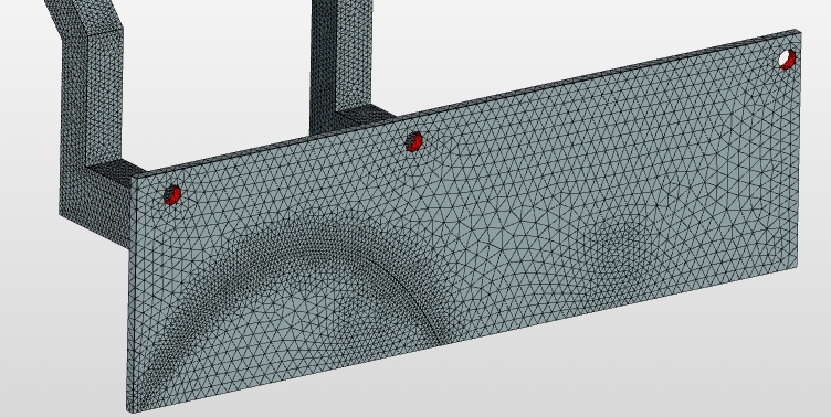
Another Fixed support boundary condition has been used at the position of the bolts.
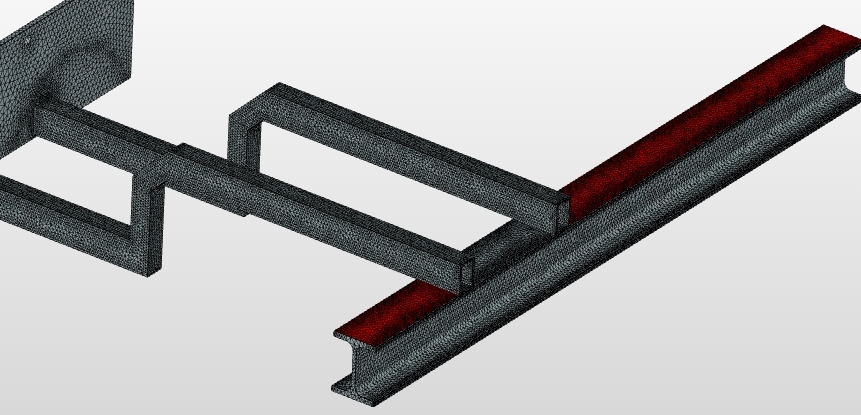
Loads
A force boundary condition has been used to mimic the loading of the battery.
Lower battery:
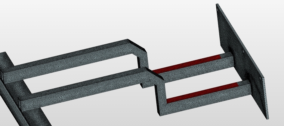
Upper battery:
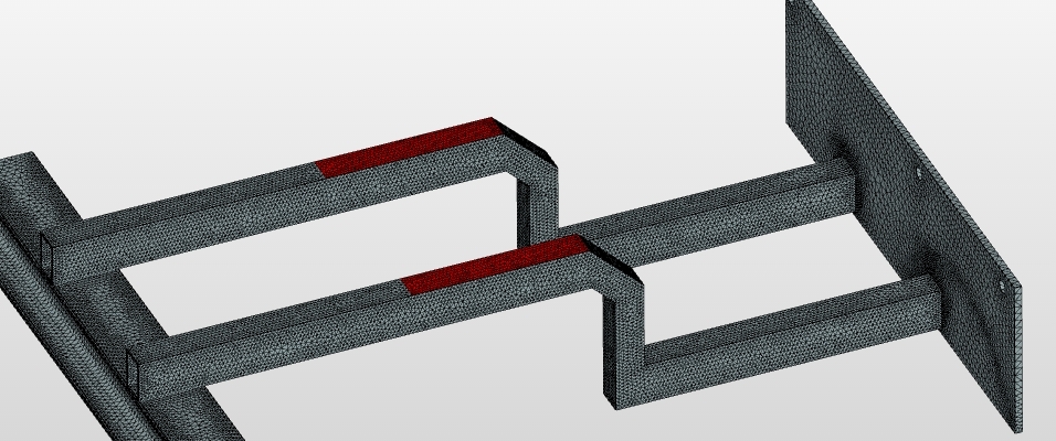
Lower Battery z-direction:
DMOC inverter:
Numerics
Code_Aster Solver
Multfront: Multfront is a direct solver of the multifrontal type.
Results:
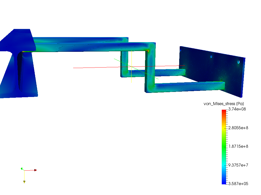
Configuration 1 - von Mises Stress
Nothing to see here, load is well under the 250MPa yield stress. Unfortunately the scale is in black and does not show. I set the max to 250MPA. The max displacement is 2mm in the 3g loads.
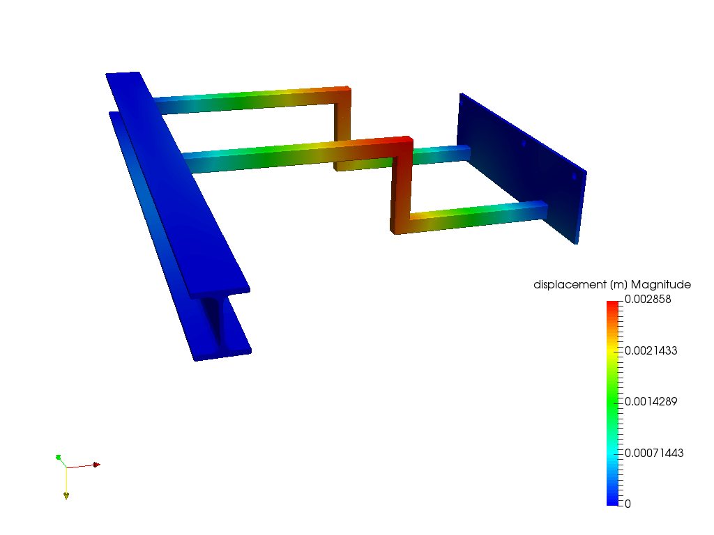
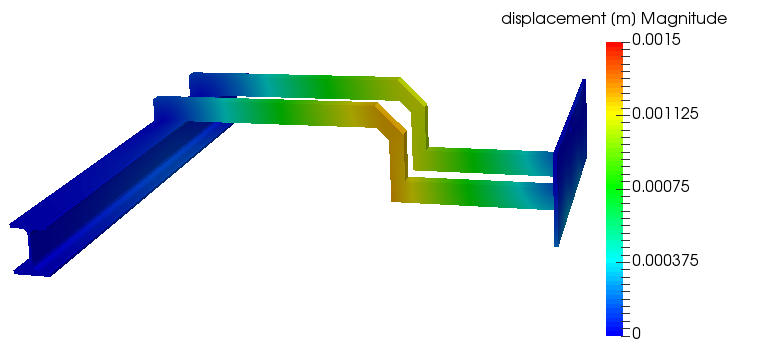
Configuration 1 - Displacements
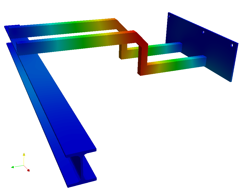
Interesting only until you look at the actual value of the red section.The displacement is a fraction of a millimeter. The system does not react symmetrically because the area where the near tube connects to the right plate is in front of the exhaust tunnel and therefore not supported as rigidly. I did do a check on the system where I fixed the tunnel area and the system did behave symmetrically.
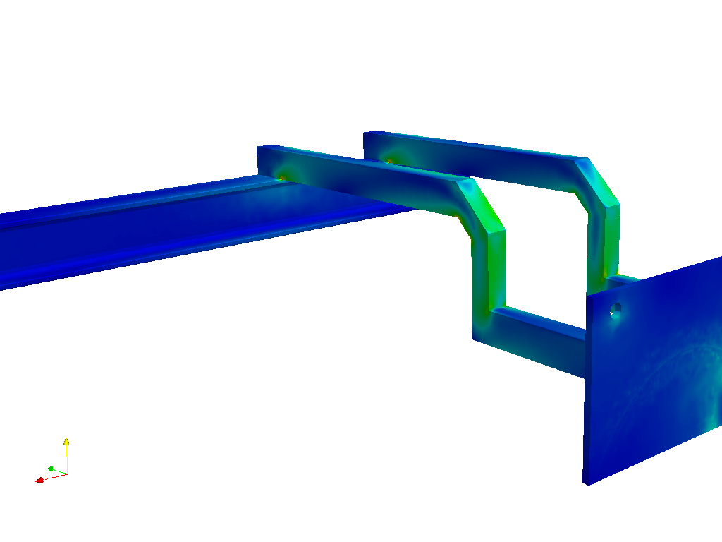
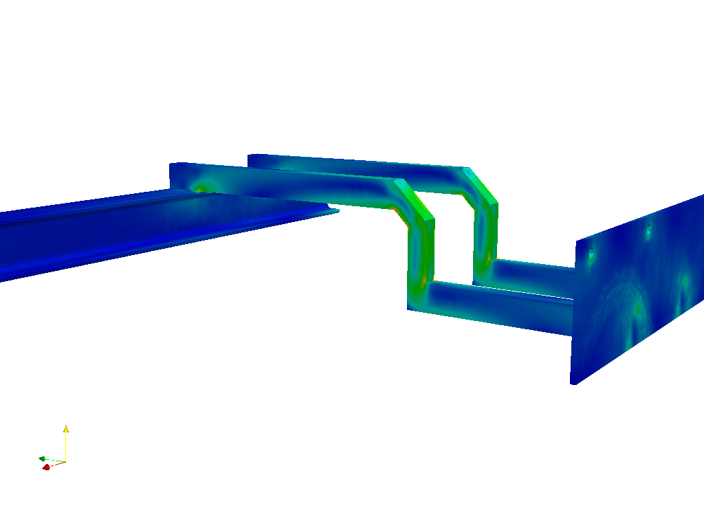
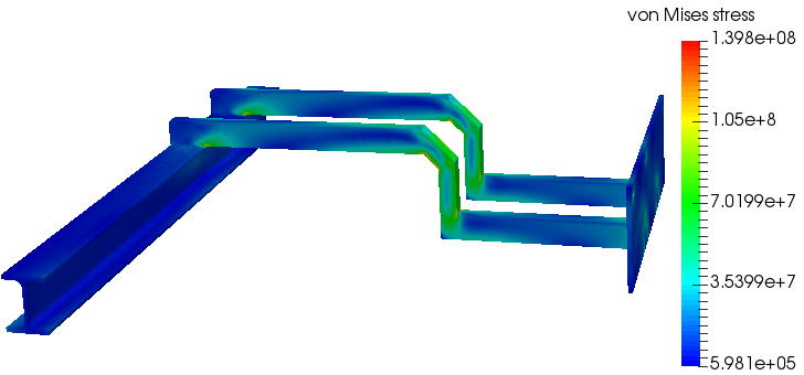
Configuration 2 - von Mises Stress
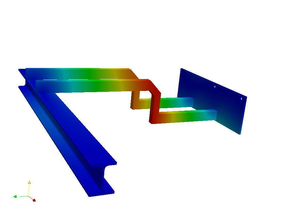
Configuration 2 - Displacements
For the values/colorbar of Configuration 1 & 2, please have a look at the project. The link can be found at the end of this post.
Configuration 3 - von Mises Stress (Pictures from the blog)
From the analysis, there will be local yielding under a 5g load, but the maximum tensile strength will not be exceeded. A crash would likely apply more than 5g to the system, but then significant other deformation of the frame has occurred at that point too.
Configuration 3 - Displacements
My hand calculations are on the same order of magnitude, SO please point out my errors if you see them.The thickness of the rear plate was 0.25", I have rerun the results, there are not surprises. I will run a 0.125" plate instead.
Modifications:
I got some feedback on the previous blog. It was decided that the stresses in the weld would be marginal. We also did a few more assembly studies and could not decide if the boxes would be able to slide in to the vehicle. THEREFORE, a slight adjustment and a few more runs on the analysis has yielded:
The changes include taller tubes, 1"->1.5" on the horizontal sections. The 45° center section, this reduced the stress on the lower side of the section from when it was 90° degrees, and further allowed the battery box more room to slide into the rear section. The front I-Beam connection also changed from welding to the center webbing to sitting on the beam, this significantly changed the area of loading for the better and will further aid the insertion of the DMOC into the bay under the hood. All around a marginally more difficult design to cut and weld, but the safety factor went up to 2.7 at yield and 3.7 to ultimate on a 3-2-1 loading. I don't see us applying a million pothole cycles while turning at speed and applying full brakes.
CAD Model:
Resources:
SimScale project:
To look at the simulation setup, please have a look at the project from @ReCalculating :
2003 VW Golf electric conversion battery frame
To copy this project into your workspace, simply follow the instruction given in the picture below.

\underline{\textbf{Visit our SimWiki by clicking on the picture}}