NP, I may have found a mesh-reduction tweak to your method I’m going to try. I’ll make copies though.
Please let me know when you have a mesh and sim setup that you want me to try for you and point me to it, when I copied project you had already go on (I think)
Please check how full your FF cache is and clean it: it could interfere with graphic operations in browser.
Okay this is pretty interesting… I’ve been playing with options on reduced geometry in this project. Apologies for the mess if you look in there, it’s a quick-iteration playspace. I’ve already said to @jousefm that I’ll clean up all these learnings into a clean project when I’m done so others can actually parse this thing without reviewing an 80 post thread.
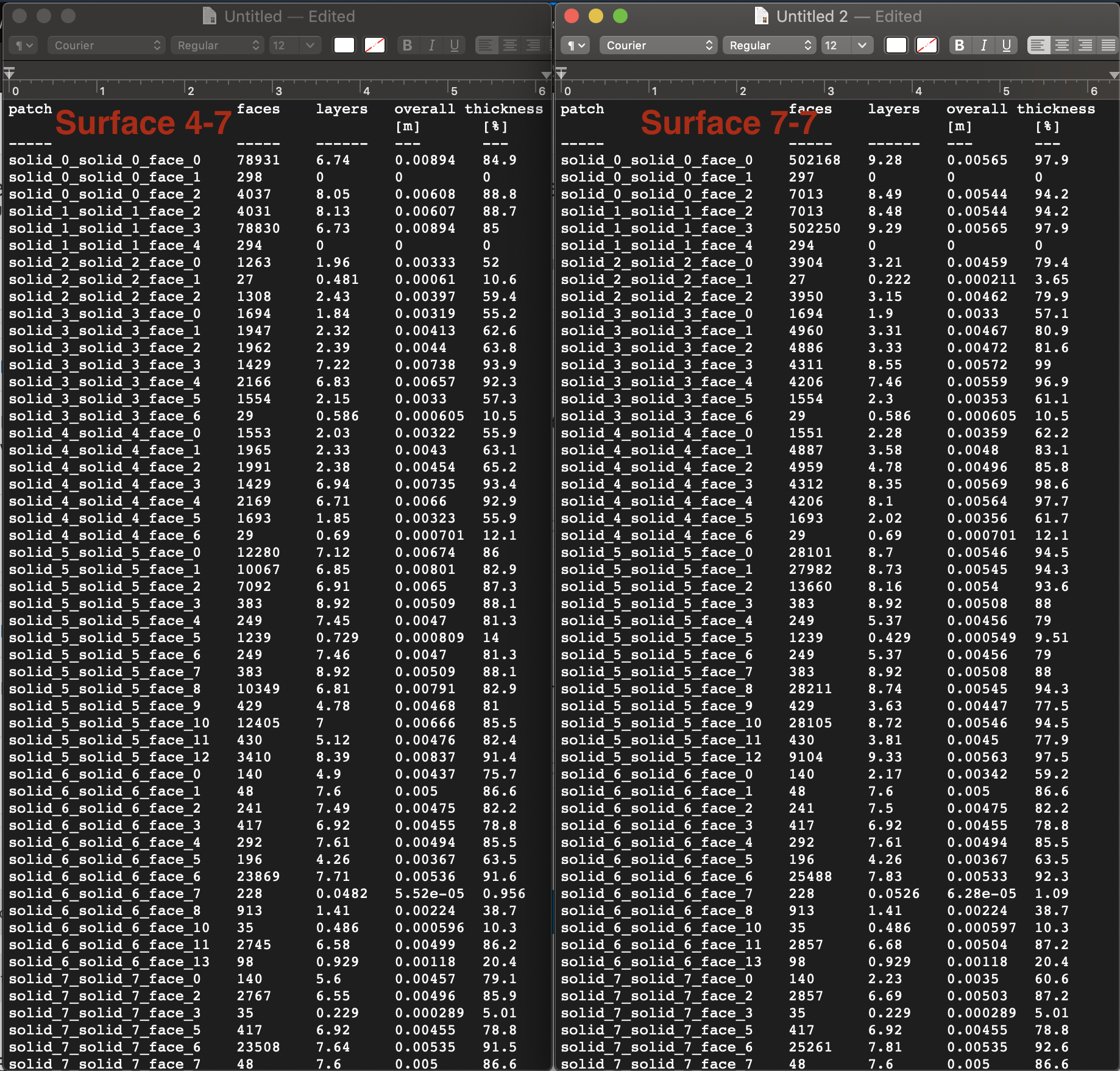
Prior mesh with good BL generation was attempting to generate 10 layers with ER=2 and FLT=0.37 (relative sizing) with surface refinement of 7-7 on a 1M square BMB. I had relaxed min determinant to 1E-7, min volume to 1E-30, and face twist to 0.001. This resulted in 90%ish coverage on most faces, total thickness of about 0.005m. Unfortunately this created a massive mesh at 25MM cells.
Following experiments in my smaller mesh project, I made one tweak: relaxing surface refinement to 4-7. The result is a 6MM cell mesh with only about 10% layer reduction! I’m now working on cat/mousing some of the parameters to improve this and will report back, but I thought this is a quite significant discovery for the Kramer method of mesh generation!
With this reduced number of cells, I think I can likely increase the number of BL layers, reduce expansion ratio, and perhaps increase my max surface refinement. We’ll see how it goes.
That 4-7 setting will likely mean that there will be significant volume mesh cells that blend into the prism cells from level 4, which may be a significantly worse gradient than 0.37 ratio.
I am eagerly awaiting a point with a completed full res Y+=1 simulation on a mesh which we like so that we can have a look at ‘Eddy Viscosity ratio’ plots.
But this is a great synergistic process here, love it ![]()
I really wish we had a way to easily get an ‘average layers/face’ value for a complete mesh which I think is a way more significant metric to judge layering than the meshing log chart (I am not saying get rid of the chart it is useful but maybe default sort should be by descending faces)… I have to take the chart to excel and perform some gymnastics to get that value now… @Retsam , as a programmer, you know how easy it would be to have that calculation in the meshing log if you know what you are doing, but then SimScale would have to adopt your modified OpenFoam code…
Right @DaleKramer, but as ‘vet’ programmer I’m used to check my assumptions quite often, even before breakfast. 
I feel that we should not spend 80% of our time messing with mesh. We should devise ‘reality checks’ with Simscale simulations. You remember that talk about ‘solid’ or not ‘solid’ few weeks ago, as I decided to use only ‘STL’ geometries for the sake of simplicity. Some guys at Simscale do not like STL at all, and expressed their opinion in our forum. Then when you found cMesh quality so good compared to Hex mesh, you asked for an option to use it in Simscale.
Now it is an opportunity to check assumption about SLT, as cMesh seems to use exclusively STL format. We really need to have a simpler, quicker, morphable, chunkable meshing tool.
For instance, I dream about optimization bench, where I define two meshes with a ‘morphing’ zone and initiate (perhaps with my genetic algos) a research of optimal CFD shape. This is just an Easter dream, for the moment. Thank you all for opportunity to peek into the mesh kitchen! 
I agree totally, but it takes a long time to see big changes here, so the more simpler ones have a better chance…
Hmm interesting ![]() I remember that Autodesk offers generative design feature but I think it optimizes for for weight and stress for FEA cases and not deal with CFD sector.
I remember that Autodesk offers generative design feature but I think it optimizes for for weight and stress for FEA cases and not deal with CFD sector.
We’ve got it already… CAC Deflected/CAC r24e27, Kramer Y+<1, no GBorg should do it with 25MM cells.
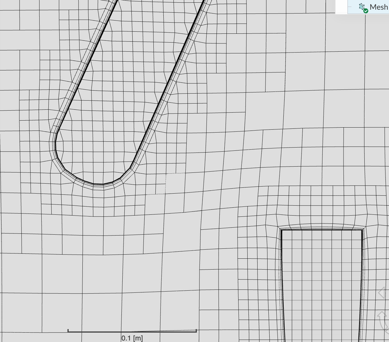
Maybe, but that isn’t what my tests indicated. See below for a shot from my variable surface gradient layer generation.
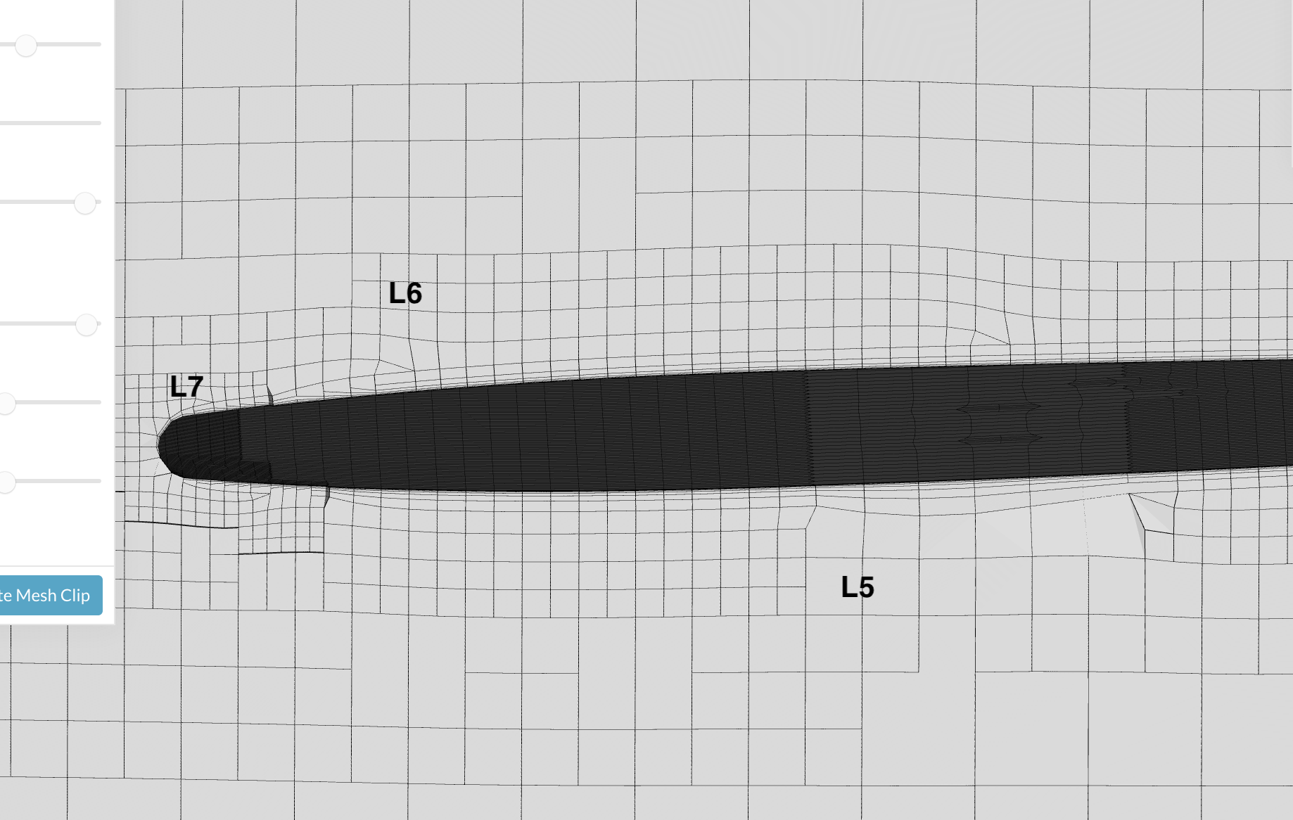
You can see where the mesh changes densities. It does get a bit larger as the refinement levels go coarser, but the close-in layers stay very similar. This was with expansion of 2, so I imagine it would be better with a lower number. Here’s a close up of the transition between levels 5 and 6 (I think).
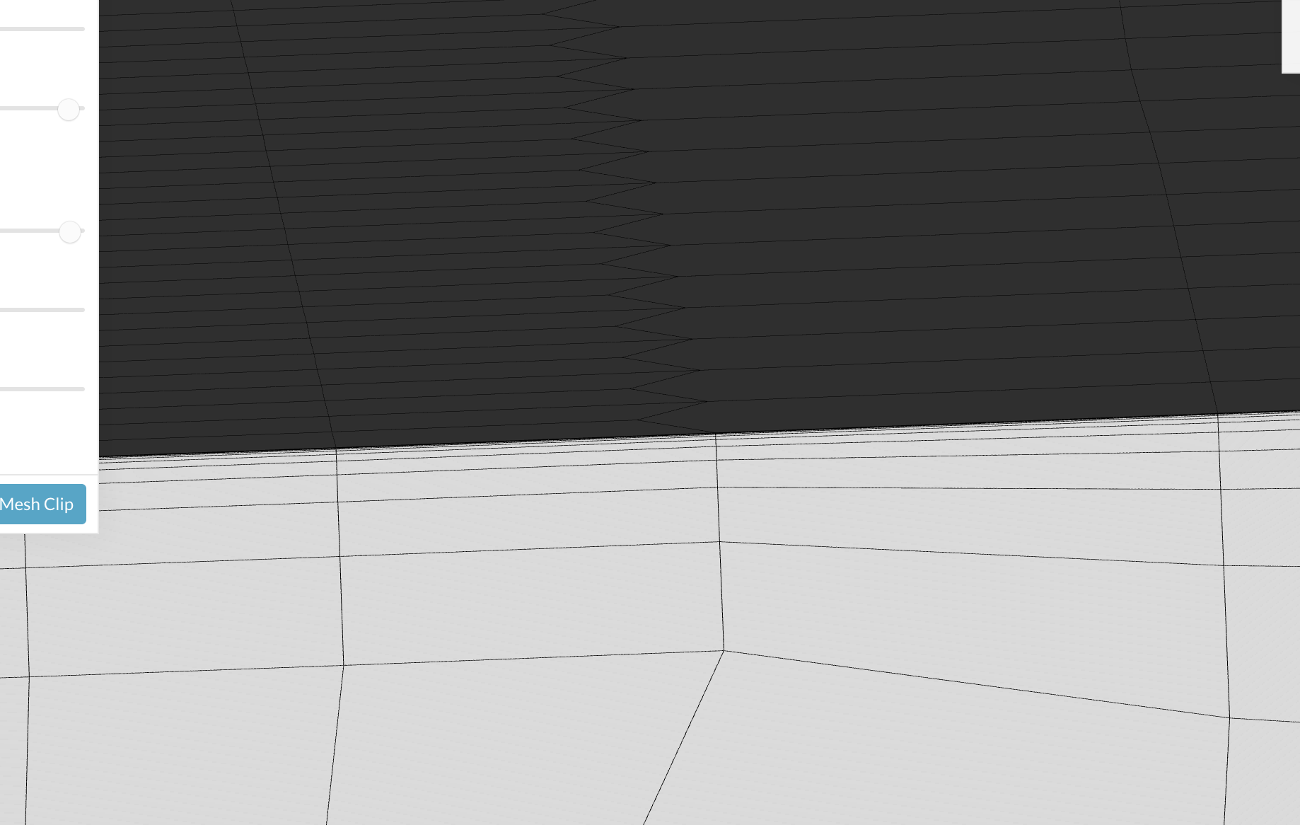
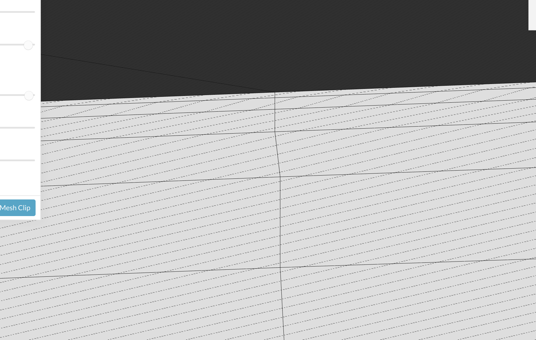
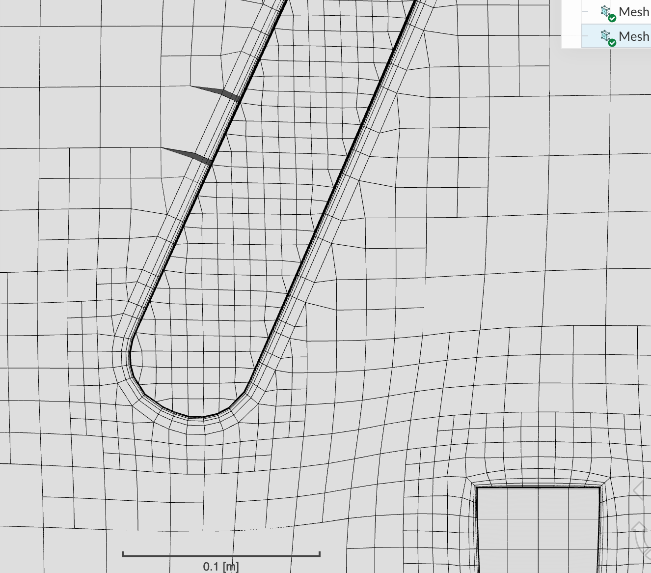
Mega zoom on that transition boundary:
It would help if in the 1st image you label one of the square volume cells as to what level it is…
I’m unsure. This was generated with 4-7 allowable so I’m assuming the leading edge is 7?
It is easy to do that, you just look at a level 0 grid somewhere further out and count one level each time it is halved (divided in 4)…
Done and edited post.
So there is one flatish surface section where prisms mesh with L5, any L4s noticed yet?
Would be nice to be able to see pressure/velocity results slices at that first image…
Worth a try like that…
I think best metric for this may be those Eddy Viscosity Plots I want
Is that is a sim with all sim parameters the way you want them?
Is that / your delimiter for sim/mesh…?
Okay there is now a completely clean simulation called “For Dale” in the list there. Have at it, big guy.
Great!
I am glad that absolute may work here, I wish I could remember what project I was on when I chose to start using the default relative layering all the time, oh well.
ER 2 is likely pushing it but I hope we have that new metric of Eddy Viscosity Ratio (EVR from now on ) plots to confirm…
Maybe I should wait on that big sim until you get sorted out, looks like you are close to trying to get a whole plane BL refinement with the fruits of your cat and mousing 
I’m running a sim on that reduced mesh now and it’s showing a similar instability to the 25MM cell mesh, which is both a good and a bad sign. Good that it’s acting like the much desnser mesh, bad that it’s not even remotely converging.
How are you going to plot Eddy Viscosity Ratio? Paraview?
Likely Paraview, but I am a total novice at that, which is why I have been hinting about EVR plots since @LWhitson2 (hint hint) pointed us to them, hoping someone else would pioneer them here at SimScale…
I still think we should do the big sim on your best full aircraft full res mesh, you just say the word… I will look now at sim you are running or last sim if it is still in Job Status…
EDIT: Wow I thought it had blown up, looks like it recovered nicely and will eventually let us have a look at EVR plots somehow. I hope there wasn’t some result we needed to add to figure EVR with Paraview…
EDIT: Interesting all looks pretty stable at 400s EXCEPT for pressure moments in pitch and roll ??
But its looks like they will stabilize by the end…
EDIT: I’d say that rudder is still pretty effective there with left yaw moment of ~2800 Nm and there is a left roll moment of ~1900 Nm with pitch moment about ~0
EDIT: IT FINISHED YEAH, SUCCESS !!! 
Can’t wait for your next post