I am working in an steel structure containing a cylinder which will have to support 10 tons of lead
My question is regarding the reaction forces on the “floor”. Feet beams will be supported using some levelers, so I would like to know about the exact reactions this levelers (two) will load
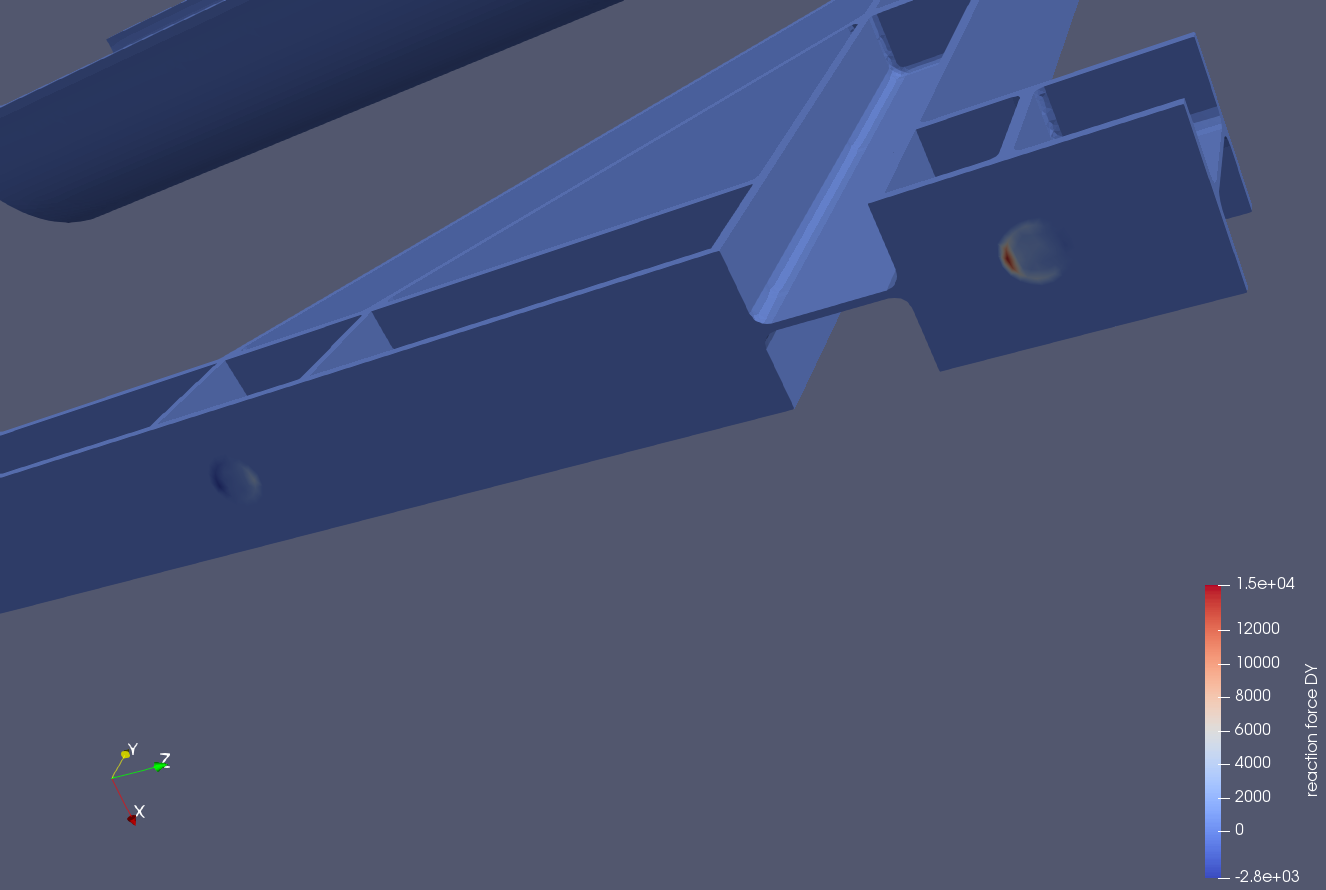
If you see the picture, it seems that both supports contain a gradient of forces, even combining positive and negative values.
On the other hand, I wonder If I can choose to not fix the rotation in the support, only translations. But I have not seen that option in the Simscale simulation designer
I assume the my error might be in the concept, so any help is highly appreciated
For the reaction forces you can define the calculation item in Result Control which has to be done before you start the simulation. The plots can be viewed based on a specific component. @ggiraldo and @ahmedhussain18 have posted an excellent step-by-step instruction here: Nodal Solution - Local
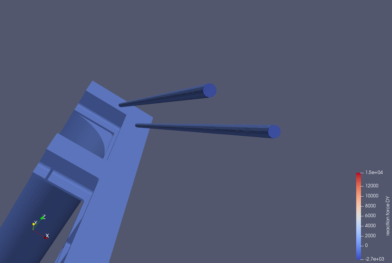
Indeed, using the fixed boundary condition on the support faces is causing the pointed effects, because it locks the rotations. In order to unlock the rotation you will need to use a “Remote Displacement” boundary condition. Create the point with the coordinates of the center of the support face and apply the desired degrees of freedom model, leaving the rotations as “unconstrained”.
Yes, I am defining the calculation of the reactions in Simsclae before the simulation. The picture from paraview is the “reaction force” representation.
So, If I understand correctly, the way I should do this is by creating in the CAD model some point in the center of the support face, and then assign the boundary conditions to those “points” (which will be treated as faces I guess, as simscale only lets you assign faces in the Simulation Designer)
No you don’t have to create any point in your CAD. All you need to know are the coordinates of that point. Then use Remote Displacement instead of fixed and give those coordinates. Fixed translational motions and allow a specific rotation. I think rotation along z in your case.
Hello @jmateo,
as @ahmedhussain18 mentioned, you don’t really need to create an actual point on the faces, just measure the center of these faces where you want to apply a free rotation via a remote displacement and put the values into the constraint under external point.
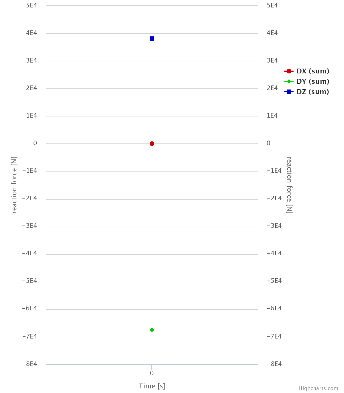
Also, you can calculate the total reaction forces on any give face directly with SimScale by adding an area result control item and choose as type sum and as field reaction force.
I made a copy of your project and created a simulation with remote displacements on the thin beams and also calculated the total reaction forces on the fixations. Check out the project here: SimScale
In paraview you are looking at single nodal values for the reaction forces, what we computed is the sum of these nodal values on all the nodes of the assigned entities - this is completely different. Nodal values are highly mesh dependent, if you doupble the nodes of a face, each node (rhoughly) gets half of the nodal reaction forces, but of course the total reaction force on the face remains constant.
You could also use a filter in paraview to calculate the sum of reaction forces on specific surfaces, but it is a little cumbersome to select all the individual nodes as the “faces” are not pickable there, only individual mesh elements or nodes.
Usually I would recommend a 2nd order mesh, especially of you have thin structures in bending. You can find several discussions in the forum about this topic. In your case I did not actually use the mesh for the simulation.
So I started setting a new simulation, and the concern I have is about If it is necessary to select the face in the filed “assignments” in the remote displacement boundary condition and why. You are setting already the point by coordinates (which is exactly the center of the circumference), then what is the face assignment selection for?
about the mesh, ok I will search about that topic. Anyway, why did you finally decided to use the 1st order one for the simulation?
Hi @jmateo,
without the assignment to a face, we would basically just apply a constraint to an “orphan” node of the system that is not connected to any element. We are basically adding a kind of multi-point-constraint to the surface w.r.t. the specified point.
I just realized that it would take too long and would not have any meaningful impact on the reaction forces anyways. You could run an analysis on the 2nd order mesh as a final check, but you should first figure out all unclear point, otherwise it is more or less a waste of (computing) time.