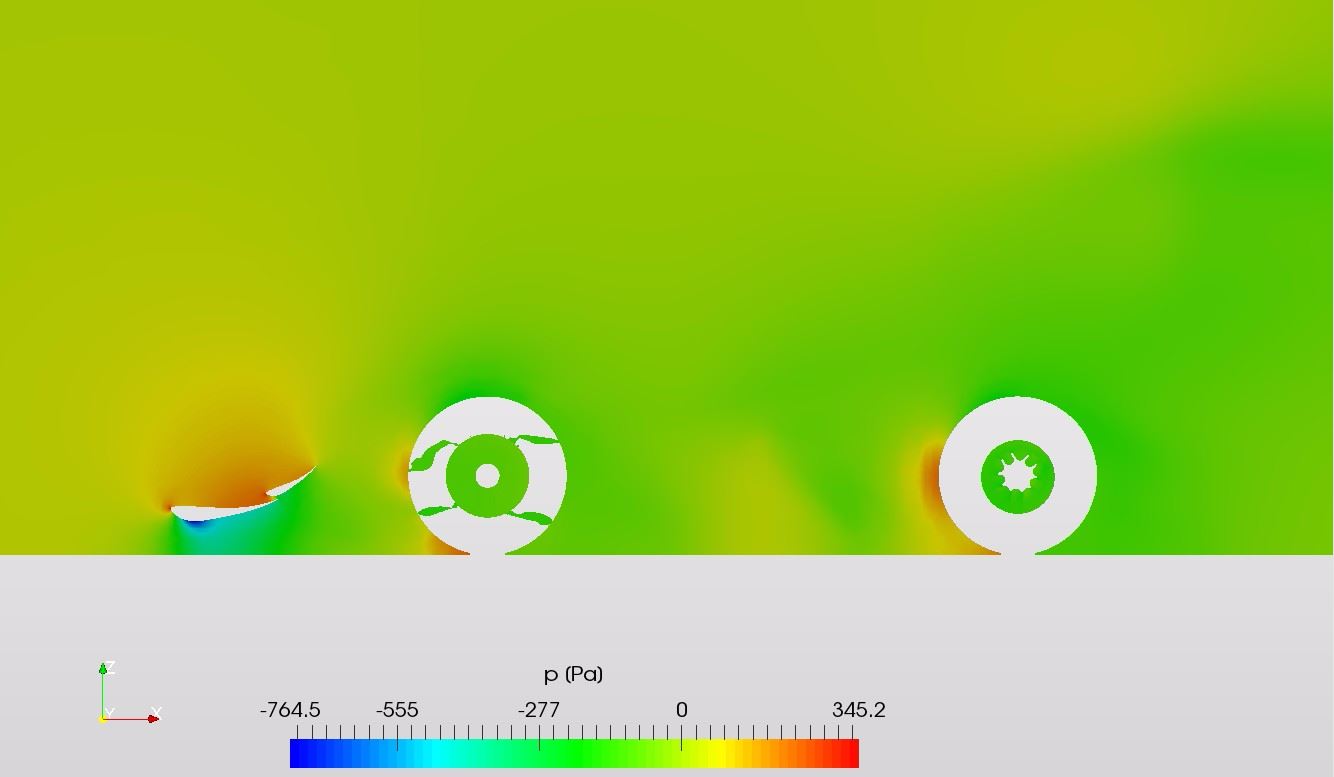
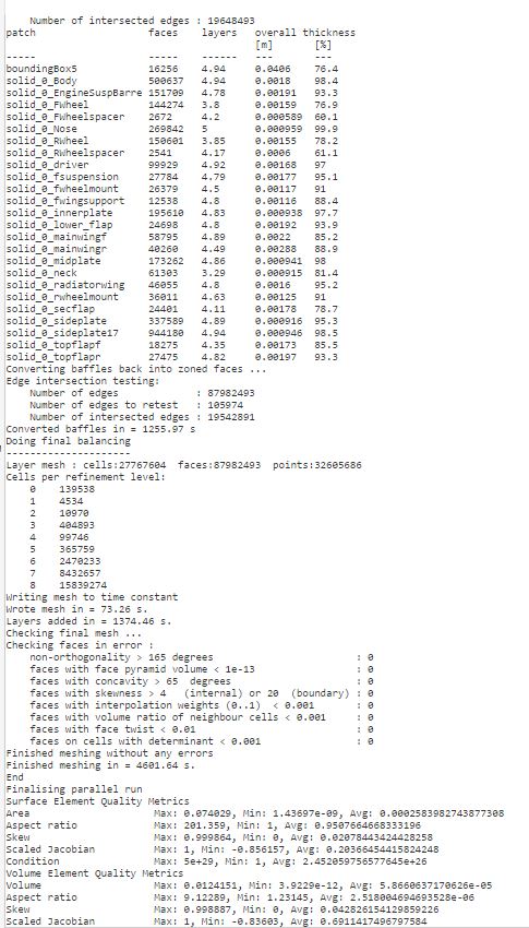
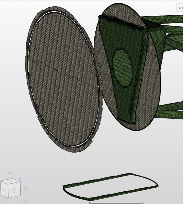
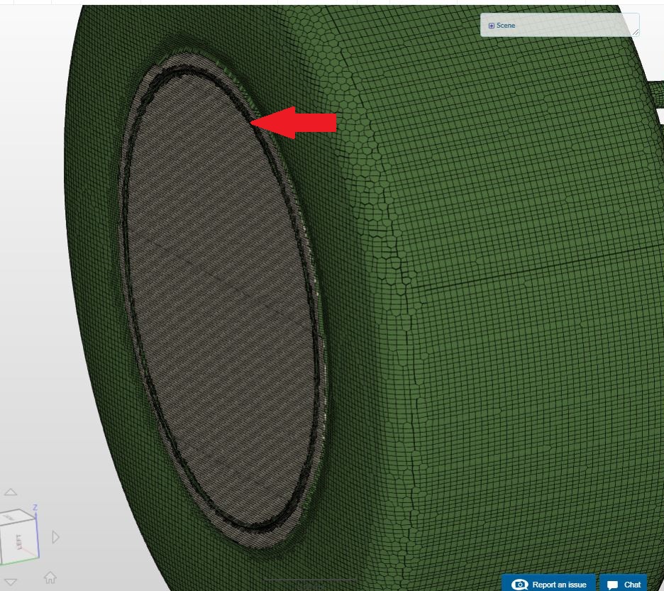
You can see, there are some wrong airzones in the frontwheel. Is it based on an issue with the CAD-geometry? I use a STL master file where are all parts included.
Usually in the marked area should be to see the radiator. In the Mesh Creator and Simulation Designer it is shown, but in the Post Processor it is missing. What could be the problem on this?
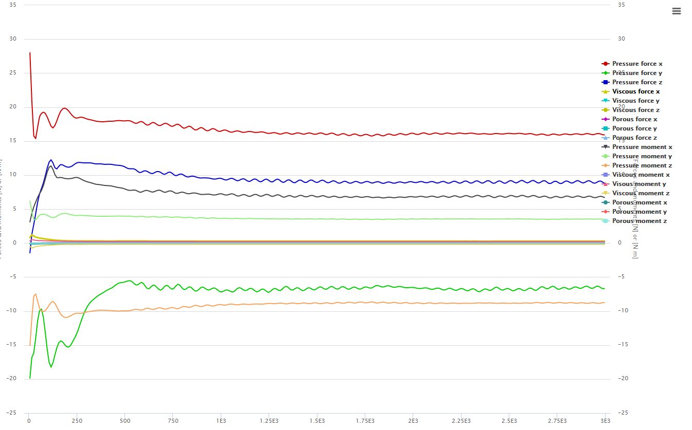
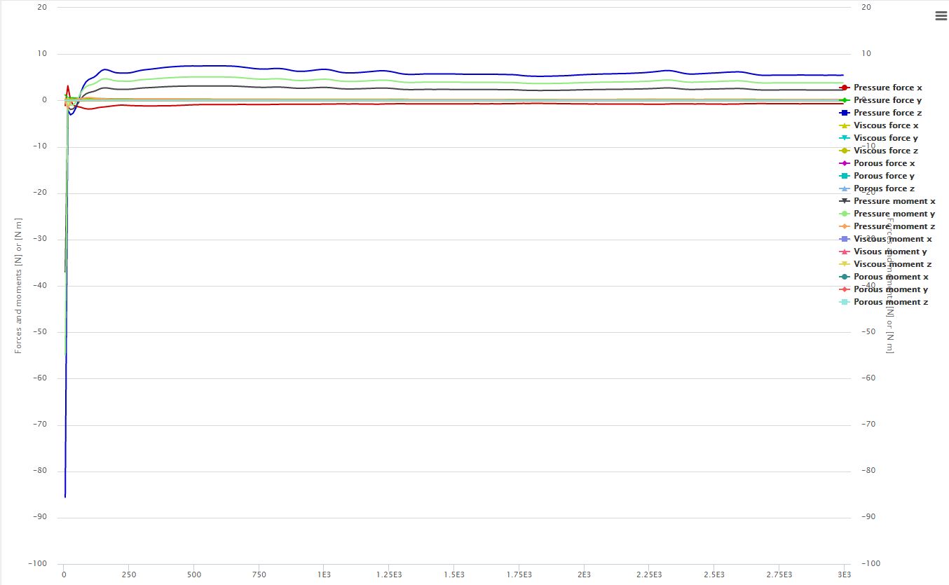
Quiet Similar to #3, the force plot of the rearwheel is not convergent. How can the setup of the simulation be improved, to get nice and clear results?
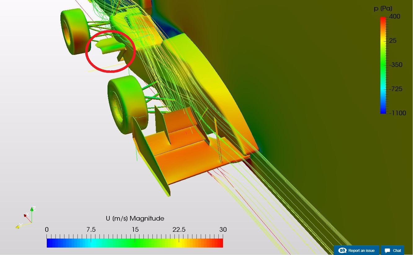
The force plot of the radiator shroud gives a negative force in x direction. This would mean, it gives a forward force instead of a breaking force. This can’t be right.
Well, a few questions and problems which need attention.
I’m looking forward to your ideas and tips for solving them.
Hey @h_koeckemann and thanks for reaching out to us!
Tagging our PowerUsers here who might give you some detailed answers to your question. Will also check these issues out and see what might cause this behaviour.
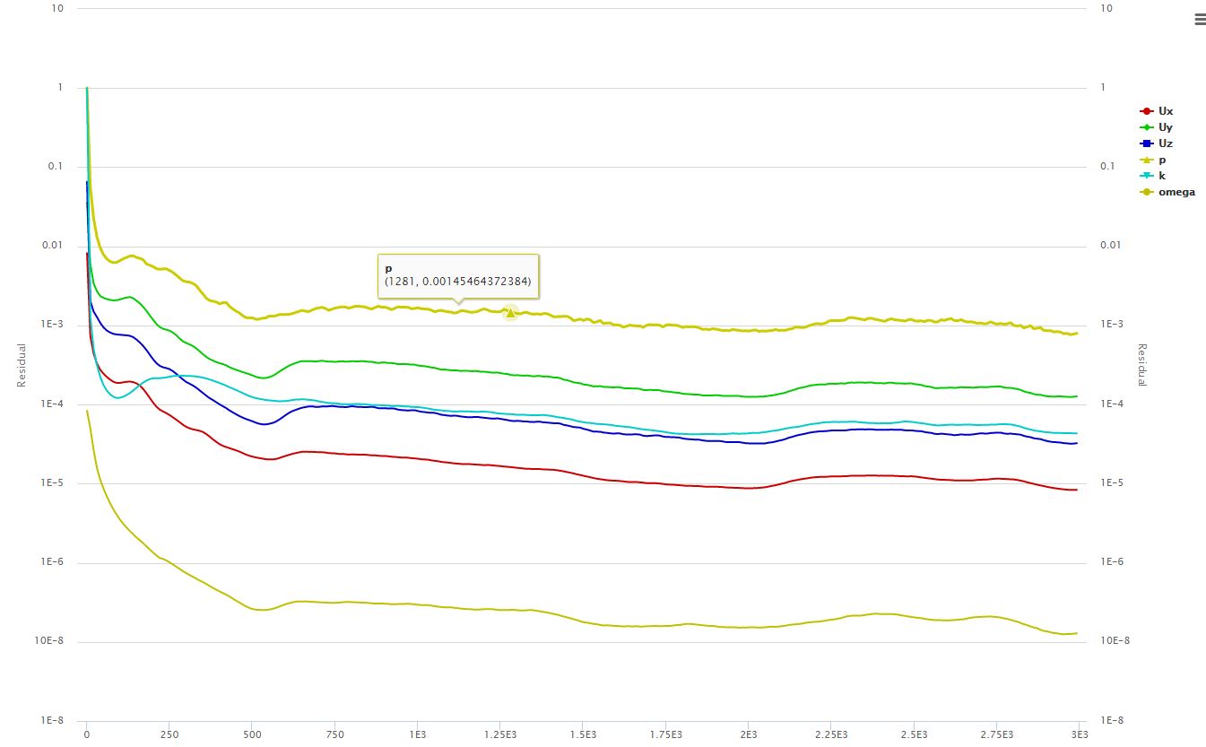
three is the same as four except you are looking at two different ways of determining convergence. Increasing the number of iterations doesn’t look like it will help you. If you decrease the under-relaxation values you will hopefully see better convergence.
Than you for the very quick responses.
I tried to get the simulation run with changed paramters for the Relaxation factor equations p,U,k,Omega to 0.2. With this setup the sim chrashed.
Now I try it again with values of 0.2 for Rel. fact. eq. p,U and 0.5 for k and Omega.
I let you know as I have a result.
Do you have an idea why it is crashed?
To go back to my first question with the wrong airzone in the frontwheel:
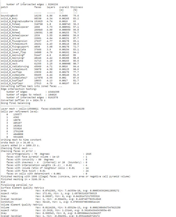
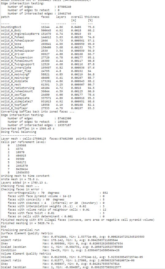
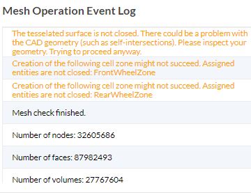
This is the meshing log for the hole car, the mesh thicknes in percentage of the frontwheel is very low. Could this be the reason for the problem #1? How can it be improved?
Hi @h_koeckemann, I was unable to make a copy but looking at your mesh there were a lot of illegal cells. This is likely the cause of your divergence. Reduce the minimum cell size allowed and increase your quality iterations, try to have no illegal cells present.
Furthermore I tried a few different setups for the simulation, but they all really need long time and the most common sim with the new created mesh and relaxation values of respectively 0.2 was killed, because the sim was running out of time.
Do you have more tips to get better results?
Do illegal cells mean illegal faces (in the meshing log)?
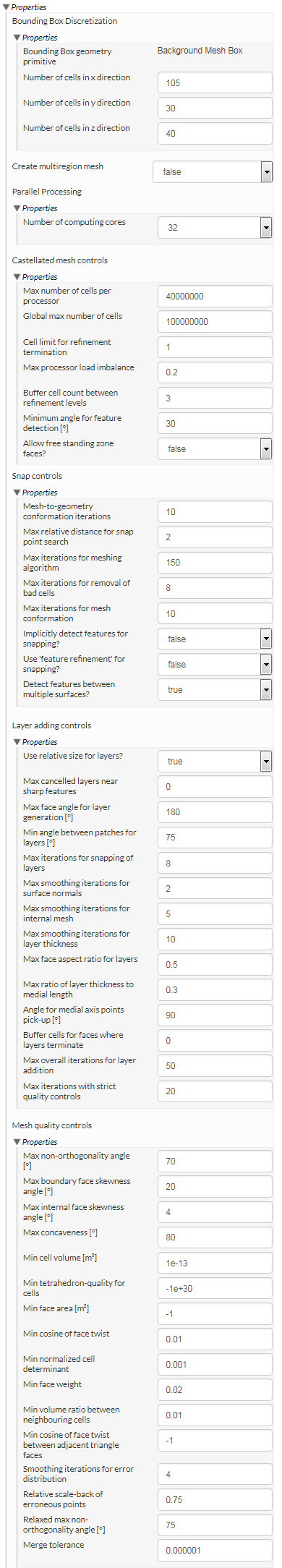
At the moment this is my meshing setup where I got the results above:
Maybe you can help me to set it up a little less computing-power-needing, but even more accurate in view to the non divergent results and meshing errors of #1.
Hi @h_koeckemann, is there any chance you can make the project public so I can change some settings and do a few mesh runs. The amount of non-orthogonality is concerning and likely the cause of numerical instability, and the number of illegal faces is a good measure as to how good your mesh is. At this stage I don’t know what is causing your poor quality mesh however the first things I would try would be to ensure the cells are the same size in all directions for the base mesh, ensure that minimum size check was off, increase quality iterations and check layer settings.
We are startet this year to make the CFD analysis for our competition car with Simscale, so it is important for us to get familiar with simscale and all its settings to make best development for the future possible.
@h_koeckemann, just spoke to @jousefm. and if you want you could give me ‘can copy’ access (you have already shared ‘view’ access) I can then copy a private copy and give better feedback?
It does sound like geometry intersection, you should ensure that the MRF is not intersecting with the wheel.
Best,
Darren
edit: the way the MRF intersects the wheel mounting doesn’t look good.
I changed the setting for the support sharing, now you have can copy acces. For sure it would be nice to get feedback to get the simulation accurate and stable working
To the MRF zone, should it not intersect with non turning zones?
I will try this soon with a changed geometry, because the simulation with the last created mesh is taking horrible much time and computing power…