Transient CFD

I did not follow your instructions and i tryed more coarse mesh and found sth. , the air flowing at 34000 m/s.
So i checked all simulations i did before, just before they failed. Found that even though i set flow at 16m/s air is flowing inside domain at speeds around 100m/s. This explains why lowering time step does not help. There must be reason why simulation ramps up the speed to such high levels.

Any ideas ?

That’s exactly the problem. You have to decrease the cell size or if you want to put it in other terms increase the finenessto avoid such unphysical behavior. Maybe @Get_Barried and @vgon_alves can help here and assure you that a coarse mesh is not going to get you anywhere if it is “too coarse” as in your case.

Cheers,

Jousef

Hi @Novak_Ondrej,

Before I get into CFL and all that, your mesh may have some quality issues. I see you have adjusted the quality controls and the mesher may not deem some cells as illegal where in fact they are or at least of very very low quality which may kill your simulation. You might want to set the settings back to default and remesh the geometry to see where the problematic areas lie so you can refine or adjust them in CAD. Refer to the figure below.

So for starters lets look at the required end time of the simulation. For transient simulations, “time” does exist so we need to consider how long the medium takes to progress through the domain. Finding this out is simple, just take your distance (maximum distance in the domain of the flow direction) divided by speed (which is your flow speed). For your case (simulation Tran_prot15_bezocasu_AC), that would be 50 m divided by 16 m/s which equals to 3.125s. So you at least need 3.125s end time to allow full flow progression through the domain. However, the simulation also has turbulence which you need to allow to kind of settle down before you call it day. This adds to your simulation time and is difficult to tell how much more time you actually need till at least you get your baseline simulation down (3.125s end time).

So considering that you’ve tried a 1E-9 timestep, you’re looking at over 3.125 billion iterations. That is, simply put, computationally wasteful.

Now we need to adjust your CFL to have a good balance between time taken and not letting the simulation crash. For starters should try to keep your CFL below 1. The solver can adjust for this via the simulation controls automatically, increasing and decreasing timesteps as needed to keep the CFL below the set amount (in our case 1). Refer to the figure below to set this. Do note that however only the PIMPLE algorithm allows this adjustable CFL under the result control. Do ensure you leave all the settings at default for the numerics.

image

Go ahead and attempt to run the simulation and observe the timesteps in the convergence or result control plots. If you see it increasing by say 1E-3 then you’re home free as it only takes about 3000 ish iteraitons to complete. However, I do think based on what you’ve tried, you may not get so lucky.

@jousefm I’m a little confused. Based on the math of the CFL condition, assuming my CFL is fixed (1), a is fixed (16) and unknown is delta T, the larger/coarser the mesh for delta x, the larger the timestep that can be taken to maintain below the CFL value no? So technically, a coarser mesh should be more able to run. The only issue I see with a coarser mesh @Novak_Ondrej would relate back to what I’ve first mentioned where your mesh quality is insufficient, causing your simulation crash due to divergence rather than a CFL value that is too high.

Assuming I’ve understood the CFL correctly, based on my visual estimates, for your largest cells, the timestep needed is < 0.025s (delta x = 0.4 m) and the smallest cell which is a semi-uninflated layer on your geometry, timestep needed is < 5E-7 (delta x = 8E-6). But if you use the PIMPLE algorithm instead, then you don’t have to worry about the timestep as the solver automatically adjusts for you.

Also the good thing about the PIMPLE is that once you’ve settled all your mesh quality and any quirks in the simulation, you can use a CFL beyond one as shown in this post here. Note that PIMPLE is the only algorithm available now to be able to take advantage of this.

Hope this helps.

Cheers.

Regards,
Barry

1 Like

Hi Barry!

Indeed one might argue that a coarse mesh will be better and indeed it is depending on what you define as coarse - too coarse will definitely make some problems and may not even converge. Additionally a too fine mesh will probably have problems with the Péclet number rather than the CFL number introducing non-physical diffusion. And as correctly mentioned you can use the PIMPLE solver where you have the option to limit the time-step to a maximum CFL number and the solver choses one automatically.

Cheers,

Jousef

Thanks for response.

I tryed making better mesh. I used default settings for quality control a refinements ant other stuff from aircraft workshop here on simscale.

Transient simulation still diverges. It seems to me like the mesh is good enough. But there is no other error that mesh indentified. But what other than mesh could have gone wrong ?

Can you please check my mesh and make suggestions ( the last one called REF_40_A15) because i cant see any problem and according to those webinars, its perfectly ok, but the transient simulation still diverges.

Simulation converges when using steady-state.

Thanks a lot

Hi @Novak_Ondrej!

Are you referring to the simulation called “REF_prot15_bezocasu_AC”? If so then the convergence looks promosing but you have to increase your maximum runtime in the simulation control - the mesh looks “perfect” :slight_smile: Attached some pictures for future simulations that can help you identify the problems easier.

\underline{\textbf{1. Where to find the problem?}}

You can click on the run (1) and then on the “message icon” (2).

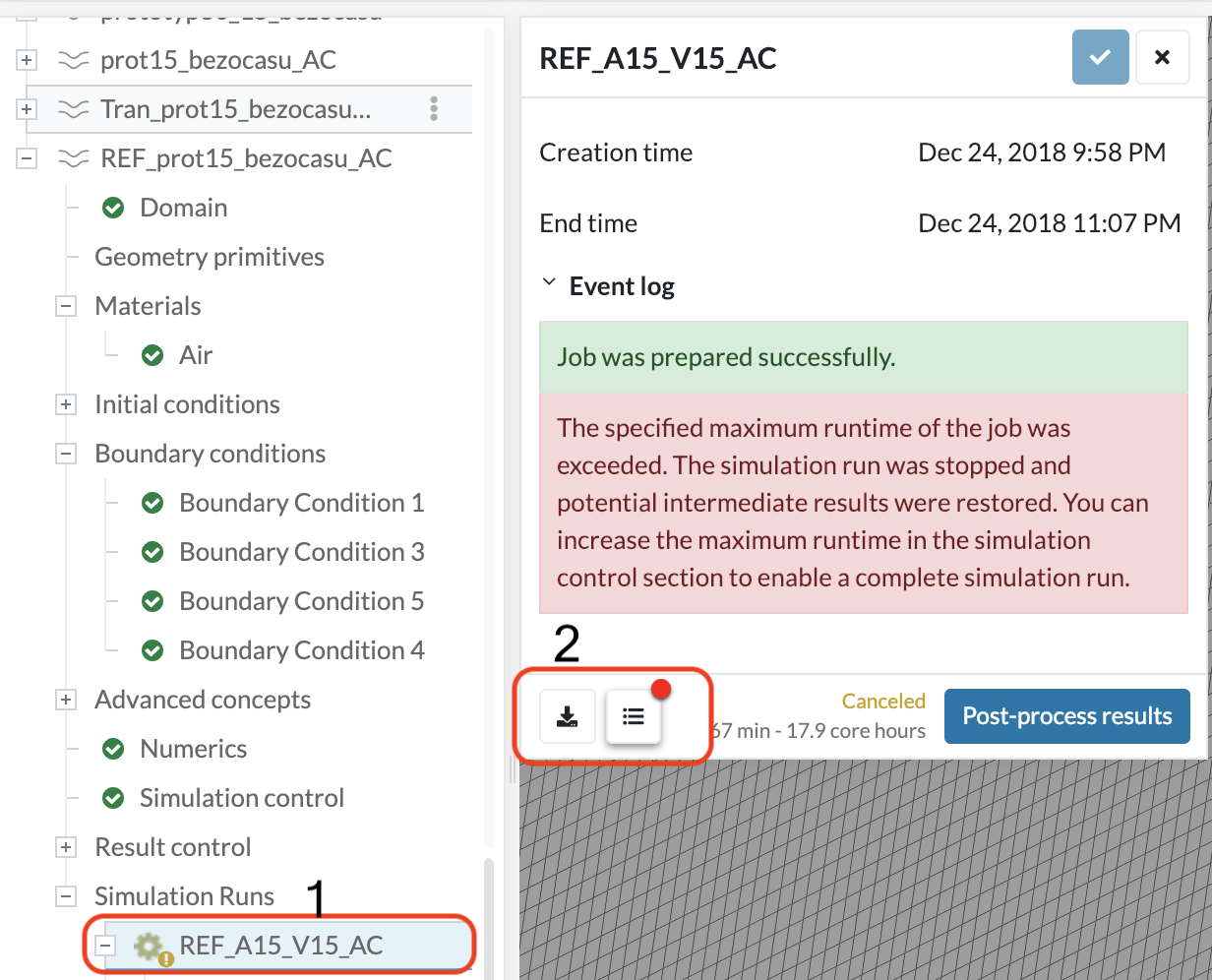
We can see it tells us there is something wrong with the runtime.

\underline{\textbf{2. Where to increase the runtime?}}

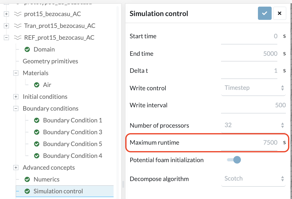
You can type in a very big number (for instance 300,000) just to make sure your simulation does not stop in the first place or use the Run continuation which can be found in this post: Platform Update 12/2018


Cheers,

Jousef

I checked steady-state simulation and its fine, lift and drag values are perfect.
But this mesh still fails for transient simulation. It diverges. I used automatic timestep adjustement on this new mesh and it failed. I must have made misstake somewhere

Hi @Novak_Ondrej,

can you tell me which simulation you are referring to? I thought it is the last one in your tree. Give me the name and I will check it out.

Cheers,

Jousef

REF_prot15_bezocasu_AC - this one is steady-state. It works fine with old mesh and a bit better with new one
Tran_prot15_bezocasu_AC - this one is transient. It does not work with old mesh and neither with new one

The transient one is problem. I tryed making better mesh and using timestep autoadjustment according to instructions here but it did not help.

Hi @Novak_Ondrej!

That’s related to the BC’s - I started a run a while ago and it is at 70% now, looks promising so far. Once it has finished I will share the new setup with you.

Cheers,

Jousef

Great ! nice to hear it works somehow

Shared the project with you @Novak_Ondrej - tell me if everything is fine!

Cheers,

Jousef

Are you sure its the right project ?
I can see you created simulation run. But its not transient, its steady state (Run 4). And its nowhere near converged. Lift force on that aircraft 18.3 kN ?
Maybe i m missing sth. but this is not correct at wall. I m trying to make transient simulation not steady state. Why your residuals are 0,3 ? it should be under 1E-3


this cant be right … but i will try using inlet/outlet instead of freestream

You’re right @Novak_Ondrej, mea culpa - already trying with the transient one :slight_smile:

And I should have mentioned that I just adapted the BC’s and not the step size. Do you have reference values for this calculation? Would be interesting to know.

Cheers,

Jousef

Good.
Well according to AVL and XFLR5 the aircraft should be getting about Fz=23,2 N and in steady state i m getting about 23N . This trend is consistent with my steady state simulations ( using old coarse mesh).
This tells me my simulations in steady state were done corretctly.
So now only transient one …

Hi @Novak_Ondrej,

as in your case my transient simulation failed and it might take a bit until I find the mistake and the right settings to make it work. Maybe @Get_Barried and @vgon_alves can give some additional input on that topic. Keeping you up-to-date.

Jousef

Hi everyone,

Running my own runs on this project. Had to remesh as the domain was much too big and costly to run. There might be some fine tuning needed for the geometry and mesh. The issue with Transient simulations is that the mesh is much more sensitive to mesh quality than steady-state, hence why both of you are running into errors or results that don’t converge/are inaccurate. So while you @Novak_Ondrej may be able to get results out for steady-state, it doesn’t mean the mesh/geometry is of sufficient quality to be able to run for transient.

Let you know the needed fixes after the runs.

Cheers.

Regards,
Barry

1 Like

Hi guys!

Just looked up some stuff about PIMPLE. With this algorithm we search a steady-state solution with under-relaxation in one time step. We move forward in time as we find a solution. We use the outer correction loops, to ensure that explicit parts of the equations converged. @Get_Barried, had a look at your setup and the simulation will probably take a huge amount of core hours. About the methodology: @Novak_Ondrej, are you looking for transient phenomena anyway or is it a simulation to see if the transient solution converges to the one from steady-state?

Cheers,

Jousef

My goal is to find, if there are some flow structures that are not steady and transient CFD is going to be neccesary or if flow is mainly steady-state and i dont have use transient simulations.