I am new to Simscale and need some help!
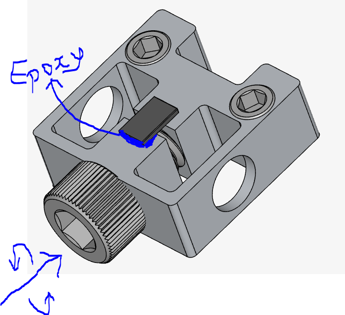
I attached a CAD model showing a driving screw (large screw on the side with a blue arrow showing the direction of rotation) and a sample (black rectangular shape).
How can I include a boundary condition that allows me to measure the torque on the driving screw?
How can I also simulate adding epoxy glue under the sample? Do I need to use a contact, boundary condition, or connector for this setup?
Hi,
From the description, it sounds like you want to analyze the torque needed to drive the screw into position (i.e. account for the interaction between the threads of the screw and the hole?
This would be a very tricky analysis due to the number of physical contacts (with friction) that you’d have. You can make one of the parts of the assembly rotate with a rotating motion BC and you can monitor torques with a “Sum” of “Moment” area calculation result control.
If you prefer to apply torques instead of defining a rotating motion, that is possible with a “remote force” boundary condition.
The hardest part of this is solving the very complex physical contacts nicely.