In the documentation, a Torque Boundary Condition is described, but I cannot find anywhere where I can create one in the Simulation Designer?
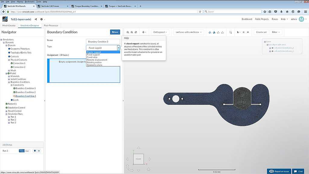
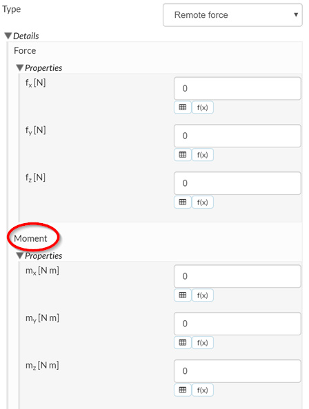
Hi @mhere, you can apply a torque with a remote force boundary condition. This is found under Boundary Conditions > Loads.
2 Likes
I saw that on your allen key project; but I do not understand where the “remote point” comes from?
You hav eit specified as 0.2m X and 0.156m in Z and I cannot relate those numbers to anything?
If you would like to visualize the location of a point you can use a geometry primitive point. In the tree under Domain > Geometry Primitives select New > Point. Then enter the coordinates of the point to be visualized. In this case X: 0.2, Y: 0, Z: 0.156.
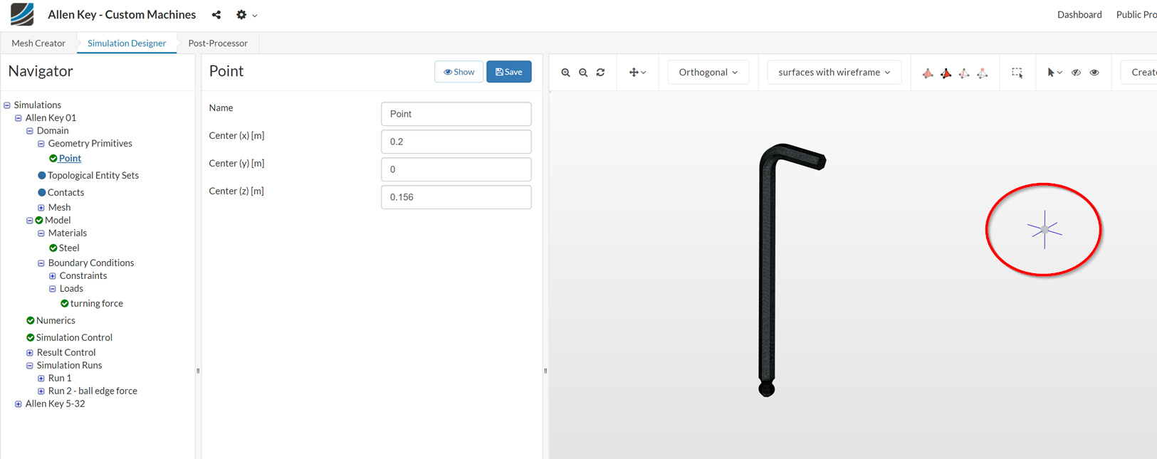
This is the location where the remote force is applied. In this case the remote force is applied to the Allen key as if an invisible pipe was connected to its short leg. This is a worst case loading condition for this Allen key.
In the case of a remote moment the remote point is the location of the moment center of rotation.
2 Likes
I suggest you start with a static simulation. Once you get good results from that I highly recommend switching to a second order mesh. Finally, if you still require it, you can move on to the more complex dynamic simulation.
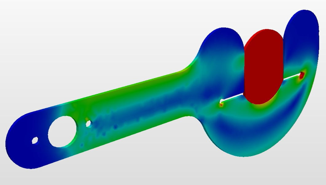
Here is an example of how to setup a static simulation.
Below is a screen shot of the results with a 5 degree rotation of the axle. The results are not valid for the axle (because of the large rotation applied through remote displacement constraint) but they are valid for the TA.
1 Like
Thank you Ben. That’s very interesting. I did not know that you could apply a time step to a static analysis (Which raises another whole bunch of questions, but I’ll hold my water and see if I can’t find some of the answers in the docs first ![]() )
)
One of the things I was hoping to get by using dynamic, is animation of the axle rotating and jaws being spread as they interact. Perhaps that was naive of me, but the hope was triggered by the animated gif of a rotating cube that is displayed in the docs:
https://www.simscale.com/wp-content/uploads/2020/06/2020-06-08_23-16-28.gif
My ideal result (and I know I’m trying to run before I can crawl never mind walk), would be an animated gif, with the displacement exaggerated, and the TA surface showing the strain transitions over time.
Even better if I could (as I’ve seen in one or two of the demo projects) cobine the exaggerated displacements with a semi-transparent ghost of the TA/axle in their original positions.
I’ve seen static projects that combine exaggerated distortion images with the undistorted render, but I haven’t worked out how that is done yet.
Anyway, thank you for taking the time to modify my project and set up the remote displacement. It surprised me that you applied this to the ‘end face’ of the axle rather the the solid itself or the connecting faces, but I guess that’s easier to select and a solid rotates as one…
M.
(BTW: I’m net expecting you to produce my vision above; but if you know it cannot be done; or can point to a project were some or all of it is done, that might save me some time and experiments.)
(Also. do you happen to know if the 3000 hrs allowance on a community account is a lifetime hard limit, or a per year allowance? I’ve already burnt through ~10%, and I’m still learning rather than getting results ![]() )
)
BTW: Do you know if that animated gif of the cube from the documentation was produced using a standard facility of SimScale (if so, I can’t find it) or by taking snapshots at each time step and then assembling them together using other software?
Cheers, M
Here is an animation of the simulation.
This was done in the offline post processor Paraview. There are explanations of how to do this on this forum. If you get stuck let me know.
I think the community allowance renews annually. You will use a lot of hours with dynamic simulations. Static simulations (like this one) run much quicker.
1 Like
That’s (almost*) perfect! 
I did have one attempt at installing Paraview, but it did not go well; I forget why. I’ll have another go over the weekend.
*Almost because (it appears that?) the axle section and/or the TA are twisting in the Z-dimension.
I assume that once I understand enough I’ll see how to add extra constraints to contain the distorions to the X & Y planes as they would be in use.
For now, I have my plate full trying to understand how to re-create what you’ve so kindly demonstrated for me. Thank you!
M.
I’ve succeeded in installing a version (4.0.1) of Paraview that works on my system, and I downloaded the results from your static run of TA3, and produced a exaggerated video (.avi format). Not as nice as yours, but its a start :)![]() However, it doesn’t offer me the option of an animated gif.
However, it doesn’t offer me the option of an animated gif.
Did you produce your .gif directly from Paraview (which could mean I need a newer version for that option), or did you convert to .gif from one of the other formats?
Thanks. M
(Also, if you have a link to hand, to the explanations of how to do this here, that’d be useful. I did a search, but keep turning up an very impressive sinosoidal distortion animation, but its all in German ![]() )
)