Simple test: body 1 mm x 1 mm x 0.6 mm, FR4 board. On top a small patch of same material that should act as a placeholder as target for a laser beam. The laser beam is directed at the top surface, heat transfer 1.53e9 W/m², equivalent to 5.5W on a 60 um x 60 um surface…
The top surface heats up within a millisecond to a high temperature. The current simulation runs for 50 milliseconds, but even after seconds there is no heat transfer from upper body to main body. Apparently the contact surface is held at initial temperature. I would assume that that the energy would be transferred to the main body and I would see the temperature rise spreading.
The contact surface between both bodies is defined, initial temperature for both bodies is defined. What am I doing wrong?
OK, I tried again and started importing a STP-Model, very simple, rectangular body 0.5 mm x 0.5 mm x 0.2 mm with a small indentation 20 um x 20 um x 1 um ( as target for the laser beam). Result: the indentation is lost. How can I tell the importer to NOT suppress small geometries? If I import a scaled-up model and then rescale in the CAD editor I get an identical result, the small indentation is lost.
That is very interesting, and I would like to have a look at both geometries. Can you please share the link to the project with the new imported geometries?
Generally speaking, the tolerance on the geometry features is given by the CAD format and the exporting program, not SimScale.
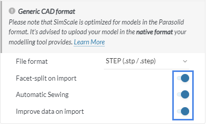
If you want to try something, you can disable the optimizations when importing the geometry:
When importing a STP file, there are no optimization options. There are no options at all, just lets me navigate to the STP file on my computer (windows 10). When I import the STP file in a CAD program I can clearly see the indentation. It is also visible in Simscale when I e.g. import a 1000x enlarged model, it is lost the moment I scale down the model by a factor of 0.0001.
Original (intended size), i.e. indentation 1 um. I finally found the import options (you have to click at the small arrow, not very intuitive), all import options deselected, the indentation is lost on import. You only see a block 0.5 mm x 0.5 mm x 0.2 mm.
Seems that I can’t post the link. I see the correct project link when I am in the editor, it is converted to the login link as soon as I post my message:
Small pyramid-shaped cutout, the idea is to simulate a trench cut into the body. The pyramid has a flat top 20 um x 20 um. This flat top is swallowed by the STEP-input, Apparently it is impossible to import geometries below a certain (undocumented) size.