I created a new simulation project called “Thermal simulation for electronic enclosure design”:
This project shows the FEA thermal simulation on an electronic enclosure design purely through conduction.
More of my public projects can be found here.
I created a new simulation project called “Thermal simulation for electronic enclosure design”:
This project shows the FEA thermal simulation on an electronic enclosure design purely through conduction.
More of my public projects can be found here.
With increasing technological growth in the field of software and electronic developments, the need to manufacture safer and more compact devices are challenging the designers across the globe to come up with extraordinary designs. The purpose of this project is to perform an FEA thermal simulations on electronic enclosures without the need for conjugative heat transfer analysis, also showcasing the reach and capabilities of Simscale. With these thermal simulations one can understand how effectively a system needs cooling. What possible design changes needs to be adopted? How does material selection influence the heat transfer behavior?
Two CAD geometries of a complete assembly of a controller is considered. One without heatsink and the other with heatsink. The heat transfers in both the cases are then compared. The detailed procedure for the simulation setup are as mentioned below:
A linear transient heat transfer analysis type is selected to compute the temperature distribution and heat flux on the entire body
Tet-dominated element type meshing is used with local mesh refinements at contact faces to ensure accurate results (An automated mesh setting of moderate-mesh fineness are applied to the chip volumes and a fine-mesh fineness are applied to the remaining faces of the body.)
On material definition, the boundary conditions are then setup with a volume heat source as a thermal load to the silicon electronic chips and a convective heat flux to the outer surfaces
The results look like:
(a) With heatsink
Temperature distribution(above) and heat flux distribution (below) for enclosure design without heatsink
(b) Without heatsink
Temperature distribution(above) and heat flux distribution (below) for enclosure design with heatsink
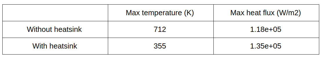
From the simulation results, we can see that the enclosure design without heatsink reaches a very high temperature value of ~712 K, thereby overheating the silicon chips and failing to transport heat effectively from its surfaces. In the other case, the heatsinks do not allow the chips to heat up to high temperatures. The heat spreads across the fins and to the aluminium enclosure thereby benefiting itself from a natural convection process. The maximum values of the temperature and heat flux are shown in the table below.
This shows that the enclosure design with heatsink:
Conclusion:
It becomes evident that the selection of appropriate materials for the conduction of heat from the heat source is one of the very important design parameter. Copper has a thermal conductivity of 1.8 times greater than aluminium. Addition of copper heat pipes can further increase the thermal conductivity to tens-of-times greater than just copper sinks. At the same time, choice of aluminium can be relatively cheaper and up-to 60% lighter in weight resulting in lesser damage to components and increasing the durability and efficiency of the electronic components.
This is just one example with heatsink alone, as to show how thermal simulation can help designers or engineers to evaluate their design using Simscale. Similarly, other thermal enclosure designs could be further clubbed together and simulated to bring in more innovative and advanced designs to the future.