Hi
I have a simple thermal analysis ongoing. It’s a tpa3116 class D chip amp. I have been in contact with TI and their specialists say the temperature of the chip with 6W heat (60W continous and 90% eff.) will be 84 degree C over ambient, and with 10W 140 degree C over ambient on top of chip.
Should I use the surface heat and use 84+20 degree? or should I lower the volume power in simulation until I get TI suggestion on surface temp on top of chip at this power.
And after this a CFD to test with airflow?
/Andre’
Hi @anorrback,
I think it depends on what you are looking for. If you looking at an enclosure box an you want to minimize the temperature in the box or the output temperature then just put a temperature boundary condition on the chip. I do this all the time. However, if you want to look at how effective the airflow is at cooling the chip then you will need to use the power dissipation and match TI’s surface temp.
Christopher
2 Likes
Thanks, that makes sense.
Could someone check these 3 simulations last runs so I learn that all faces are selected in a correct way for contacts, wall cooling, heat in the chip, materials and so on.
Hi @anorrback,
From what I can see it looks like everything is setup correctly and you are no longer getting a temperature of over 900 degrees. 
The only two issues I see are fairly small. When you define the contact surfaces between the chip and the PCB you are using the entire top surface of the PCB. It would be better to go into your cad model and split the top PCB surface so it has a separate surface under the chip. The same applies for the heat sink to chip interface. I believe since you have the top of the pcb defined as a contact surface, it will not be able to dissipate heat to the air. It will be treated as an adiabatic wall. This should not make a big difference but it is worth looking into.
Enjoy,
Christopher
I took down the heat flux power until I reached the right temperature on top of the chip.
I did one simulation without splitted PCB face and one splitted but saw no difference. I did not test to split the cooler face.
How can I see in postprocessor if the heat is moving away from the PCB or if it just acts as contact tho whole top of the PCB.
Hi @anorrback,
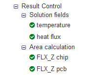
If you switch to the advanced thermal analysis type you get a lot more result control options. This gives you the ability to measure how much heat is lost from of each surface.
I’ve made a copy of your project and set up a example simulation for you. I’ve not checked if the results make sense but it should at least demonstrate the idea.
Is this what you are looking for?
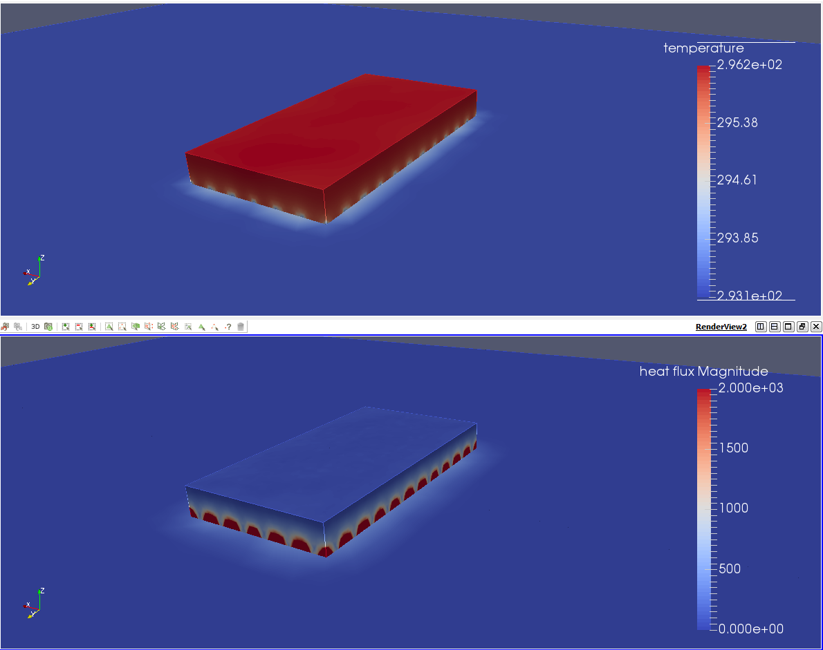
Here is a plot of temperature and heat flux. It looks like there is a problem with the mesh under the heat sink. This can probably be fixed by applying a mesh refinement to the PCB under the chip.
I hope this helps.
Regards, Ben
1 Like
Hi @anorrback,
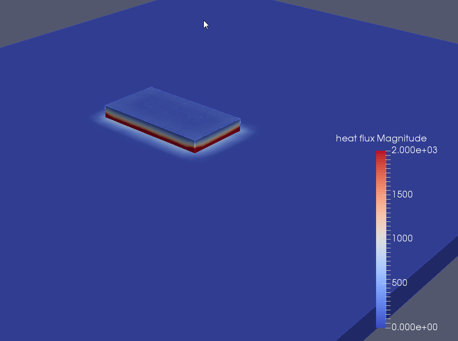
Swapping the contact entities (back to what you had originally) fixes the heat flux problem at the boundary between the chip and pcb.
1 Like
Hi @anorrback,
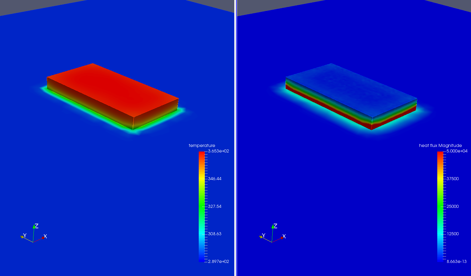
In my example project I’ve increased the chip volume heat source from 5e6 W/m³ to 126.58e6 W/m³. This was your original value and it’s a value that seems to be the right order of magnitude (from data sheet for the chip). This results in a chip surface temperature of around 90°C.
Do these number make sense for your application?
Here is a screen shot of the results.
1 Like