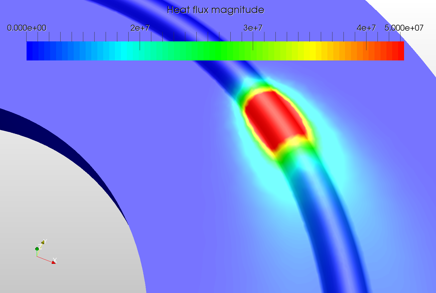
in this weeks spotlight we will have a look at a heat transfer simulation of a Laser Beam Welding process by our Applications Engineer @ahmedhussain18.
Introduction
Laser beam welding (LBW) is a welding technique normally used to join pieces of metal by using laser beam. The welding process is performed by indenting a concentrated heat source provided by a laser beam over the area that needs to be welded. In this project, the Thermal Analysis module of SimScale was usedto demonstrate this process.
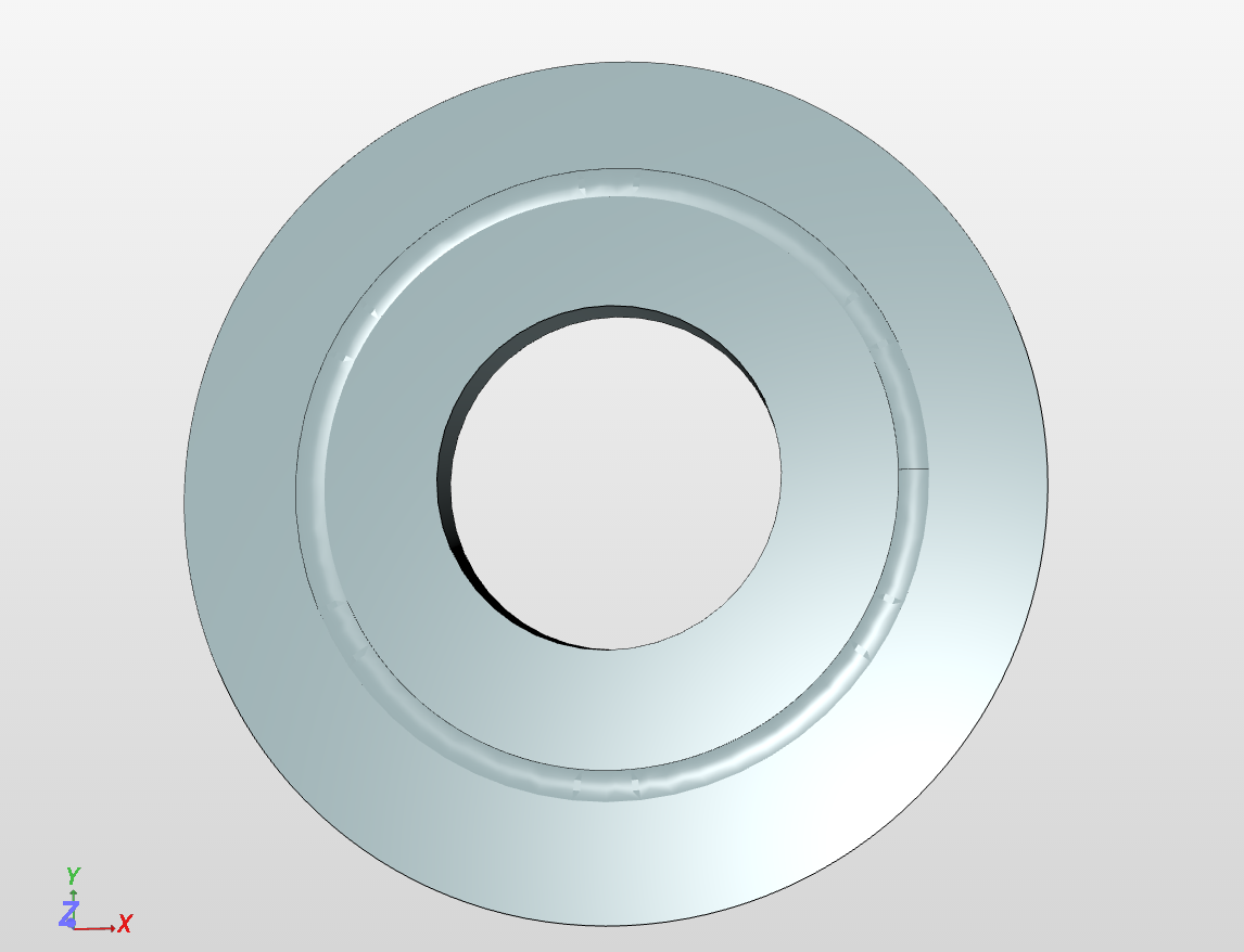
The main focus was on the use of surface heat flux boundary condition to produce the effect of a moving heat source. The geometry was a simple circular plate on which a small hump in a circular fashion was made to represent the welded area.
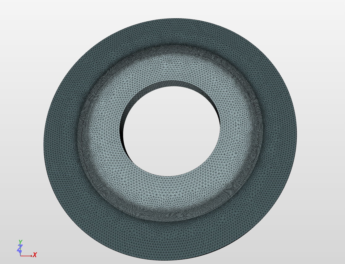
The geometry was meshed using tetrahedralization with refinement on SimScale platform with much finer mesh over the welding area. The mesh is shown in figure below.
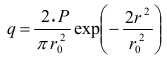
Steel was selected as a plate material. All the surfaces of the plate except the bottom surface were considered exposed to air by giving the convective coefficient value of 5 \frac{W}{m^2*K} at room temperature i.e. 298.15 K (25° C). In order to have a moving heat source in circular fashion, the welding area was given a surface heat flux by using a Gaussian power distribution function represented as:
P is the power of laser, 2 kW in our case.
r_o is the radius of laser beam, 0.003 m (3 mm) in our case.
r = \sqrt{(x-x_o)^2+(y-y_o)^2} is the radial distance of the beam from any point. Here, x and y are x and y direction of the coordinate system respectively. xo and yo are the terms used for defining the motion. In our case, x_o = a + R*cos(2 \pi v_\alpha t) and y_o = b + R sin(2\pi v_α t), where;
a and b are the x and y coordinates of the circle center, in our case (a,b)=(0,0).
R is the radius of the circle, 0.035 m (3.5 cm) in our case.
v_\alpha is the angular velocity of the beam, 0.167 \frac{rad}{s} in our case. The actual velocity of the beam can be calculated by v = 2\pi R v_\alpha which gives v ~ 0.037 \frac{m}{s} (~2.22 \frac{m}{min}.)
t is time step which is 6 s for a full revolution with timestep length of 0.06 s in our case i.e. cos(2\pi) and sin(2\pi) occurs when v_\alpha*t = 0.167 \frac{rad}{s} x 6 s = 1 rad
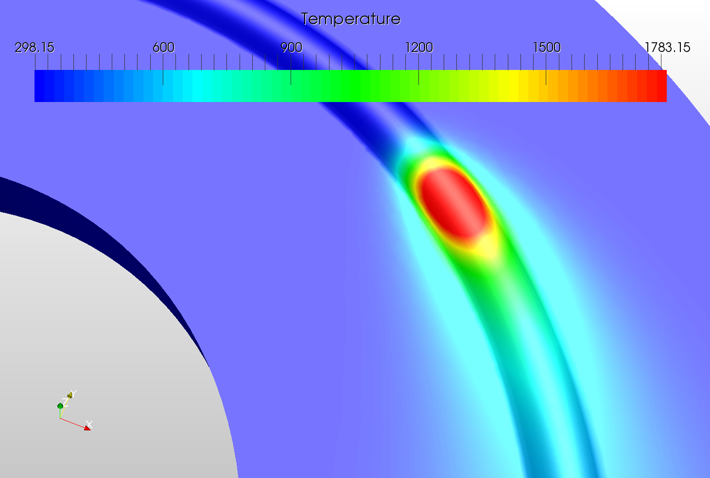
Although the temperature of the laser beam was much higher than the highest temperature of the legend i.e. around 2500 K, the trimmed value of 1783.15 K is used since it represents the melting temperature of steel.
SimScale project:
To look at the simulation setup, please have a look at the project from @ahmedhussain18 :
interesting. I am doing more or less similar things in my Ph.D, but without welding. There are a few things I am interested:
a) The source is only applicable to the x-y plane, right? So no LASER can be applied to a caricatured surfaces.
b) The laser source is moving, so do you interpolate the heat insertion during the time steps? I don’t think so, right?
c) The laser profile does not look too realistic, but maybe it is based on the fact that I am always using aluminum which has a much higher thermal conductivity.
d) Do you use a FEM solver or FVM one? I guess first one because you are related to the topic of FEA.
e) Why did you use 0.06s ?
Yes, in this case the laser is applied along x-y plane keeping z constant. If the surface is tilted along z, you then have to take in to consideration the z plane also to have a consistent laser heat distribution. I have performed that case also, have a look here:
Yes, you are right, the laser heat source is moving only. Whereas, the heat flux remains constant.
This is a typical Gaussian power distribution formula.
Yes, FEM solver
In order to capture the laser motion properly. Using a coarser time step can lead to odd temperature and heat flux distributions. So two very important things here is the much finer mesh on the laser impacting surface + finer time stepping.
thanks for your reply. I was just interested in your formulation and thoughts
The Gaussian shape is correct however you can modify this formulation but it does not matter here. What I got is:
a) You can not apply this BC to a 24,6° inclined plane, right? Only normal to the ordinate planes otherwise you need a transformation of the Gaussian function and I guess you did not do it, right?
b) Your answer to e) was not what I wanted to know. I wanted to know why you choose 0.06s ? I guess it was just from your feeling and tests, right? The problem you have here is the missing interpolation of the heat impact to the surface during your dt. If you time step is too large, your heat source is to far a way (jumping from one position to another which lead to your non-continious mentioned temperature profile -> no interpolation). However, I am still interested if used a formula for dt. I guess it was your own decision after a few tests
Kind regards and thanks for your reply.
Tobias Holzmann
By the way the mentioned “hardening” case gave me more information. I am right:
a) Gaussian is applied to x-y plane
b) Question to the name - where is the hardening part? Or why did you named this project “hardening”? It is just a local ‘heat-treatment’ without any calculation about material property change or is it also available?
Yes I think this is not possible with this formulation. This needs little tweaking.
I used 0.06 s as it looks reasonable. As this was just a demo project but not some kind of a validation, I used a value such that I don’t spend too much computational resources here. But of course making it finer will give better results.
But also can be applied with the change in z.
The name of the project was given by that user. Hardening effects are right now not possible. At some point it can lead to the transformation from solid to liquid domain or something and may need some more advanced physics solver. The user was only interested in to know the depth of laser beam for a specific power source.
an anyone help me with a circular shape laser beam heat load. I am new to simscale and wants to know how to define heat load on the metal surface if the LASER beam is 1 cm circular beam exposed on a metal surface. The LASER is ND-YAG laser with pulse width 200nm and power is 5W. Any help will be appreciated. Thanks.