Taming relative meshing | snappyHexMesh

In this topic I’d like to focus on snappyHexMesh and work out selected parameters related to it. Generally they are described properly, but I don’t quite understand some of them. The other reason for this is that I’m used to dimensional meshing (like probably most users; especially elder ones) and I found this relative approach really tricky.

MESHER PROPERTIES
Let’s start with settings and try to clarify some of them:

Castellated mesh controls:
maxGlobalCells |it means that regardless of mesh size maximum number of cells qualified for refinement will be this number? The default one is 2e6 – is it optimal for most cases? I guess it’s bounded with amount of memory needed for refinement, so I should be careful with bigger numbers, yes?

maxLoadUnbalance |is this parameter responsible for communication between processes in parallel meshing? I mean value zero enforces perfect match of meshes generated by particular processes and changing it into one I risk intersecting elements and double volumes, right?

allow free standing zone faces |could you describe it in a different way? Or even support it with some picture?

Snap controls:
nSmoothPatch |the greater value the better surface mapping, right?

implicit Feature Snap |if I switched it off and defined individual surface refinements to bends, chamfer etc. would it be the same? Or this automatic option is better as it automatically refines other features such as holes, sharp edges, steps and so on?

explicit Feature Snap |when should I use it? For instance: I’d like to investigate temperature layout in closed box with a base of electronic board. Then this feature will help to identify all that tiny elements on the board (processors, capacitors, resistors etc.) and mesh them properly?

multiRegion Feature Snap |I should use it in case I had multiple volumes (domains) that I’d want to simulate as one with interactions between them? Then this feature will secure proper mesh connections?

Layer adding controls:
nGrow |zero means Boundary Layer should end before it reaches surface with no BL? So for 90 degree corner (internal mesh) it means BL reduction by stair stepping, right?

slipFeatureAngle |it’s to avoid high skewness in BL regions? If yes, then I should keep this value rather low, right? What is a reasonable border value here? And finally what does it mean “allow mesh to slip at non-patched sides”?

GENERAL QUESTIONS

  1. Bounding Box element size is level zero or level one?
  2. How to control boundary layer in Automatic snappyHexMesh for internal flow?
  3. Generally ‘relaxation’ means ‘smoothing’?
  4. Meshing process is top-down and BL is generated after? At least this is how I see it looking at the text log.
  5. Why in Meshing Log I have information Finished meshing without any errors together with a list of quality controls (all okay) and in Mesh Operation Event Log notification Mesh quality check failed. The mesh is not OK. What’s more, I can still run a simulation with such mesh. How should I understand it?

Now, if there is someone who could clarify above-mentioned I’d be grateful. I just hope I don’t ask silly questions. I really want to control it fully and move my focus on simulations settings. So far meshing cost me most of my core hours and despite I tamed it quite well (at least I think so) there is still some work to do.

2 Likes

Okay, so now it’s time for problems solving. In this post I’d like to focus on Boundary Layer creation and unexpected local refinements as I think this is what prevents me from obtaining desired convergence in my simulations.

In short: naturally I started with very simple geometries and after (probably all) rooky errors I decided to move on to proper tests. At first, on my workbench, I took Remotely Operated Vehicle (which is a part of my PhD). In this case drag calculation means single phase and incompressible flow simulation.

The mesh I was able to run my simulation with I obtained really fast – I got first results within something like two days. What’s more, outcomes from different meshes are there or thereabouts in terms of correlation to experimental data. The problem is however that the mesh (BL especially) is strange at some places. Below I’d like to present few selected pictures and show you the problematic areas.

I tried to keep the same pattern, so the vehicle is highlighted red, the mesh is grey and the BL I coloured in blue.

TRANSPONDER AREA
ROV cut in half, view from the inside

ROV cut 45 degrees, view from the inside

ROV cut 45 degrees, view from the outside

BOW AREA
ROV cut in half, view from the inside

ROV cut 45 degrees, view from the outside

AFT AREA
ROV cut in half, view from the inside

Does anyone have any ideas? What could cause such mesher behaviour? Why it loses BL without any reason? Why there is such a big refinement at bow surface?

I think I understand all the most important features in mesh settings, but maybe I keep missing something… Also if you need more pictures or want me to describe something in more details feel free to write.

1 Like

@Maciek, this is awesome! Thanks for posting this - let me prepare a couple of points and I’ll then post it here! Great!

Hello - further meshing tests.

I’ve spotted something on ROV’s hull elements and decided to check it with a use of a simple geometry. Deliberately I took sphere (ball) and torus elements. And to make two things at ones one ball and one torus were cut into half, the other weren’t. The reasons for this were as follows:

Missing torus elements | I remember that in the past it was quite a common problem while importing and exporting geometry. Changing format from one to another often led to missing parts. What they had in common however was lack of clearly defined generatrix for this particular elements – torus is an excellent example. So, below is what I saw at the first time.

Solution to this is very simple: just cut element anyhow to make additional edges which help to identify the shape.

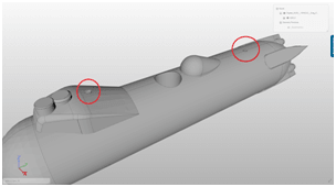
Strange mesh refinement at bow and BL issues | I’ve mentioned about it in my previous post. Later on I changed input geometry and I noticed that unexpected refinement occurred only in situations when I’d cut bow section into half. In case where I had left it as a semi-sphere the mesh was okay.

Now quick, simple test and its results:
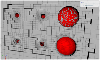
Basic geometry

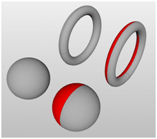
Elements in the foreground are the ones cut in half (highlighted). What’s interesting, importing torus as an independent element program automatically split it into two parts – well done.

Sphere however maintained its generatrix from CAD program (which I guess allowed shape identification) – super.

Unfortunately, Boundary Layer generation went worse :-/

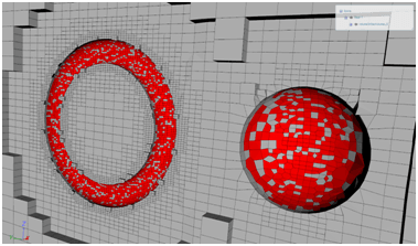
Below we have overall view of surface mesh at particular elements. Please notice one very important thing I have also experienced during ROV mesh generation (!).

I have no idea what it is. It seems that mesher splits surface according to some strange scheme and then assigns mesh in this peculiar way. I would say it has an influence on results. Except problems with BL I have noticed significantly worse residuals too. - Anyone has any idea or explanation to this?

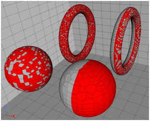
Volume mesh – cut at XY plane (so that all elements could be seen).

This time I didn’t bother myself to colour BL. As you can see proper BL (I have no objections to it) was generated at cut sphere only. The other sphere and both torus have no BL.

Volume mesh – cut at plane YZ (picture showing two previously cut elements).

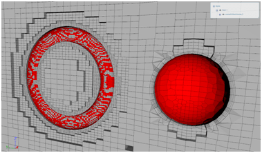
Volume mesh – cut at plane parallel to YZ (picture showing two previously uncut elements).

1 Like

@Maciek, great input! Thanks for your efforts! I am not finished with the updated documentation for snappyHexMesh yet, but I expect it to be done soon which then should clarify a lot of the questions you asked in your first post. I’ll directly link it here once being done.

Regarding the troubles you had: Any chance you could share me the projects where this behavior happened? That way I could check on it in more detail.

Best,

David

Here you are:
https://platform.simscale.com/?publiclink=5cd7f0d5-10a5-4c67-be29-0b58bc5b9f08

Imported! Will look into it probably today or tomorrow and get back to you.

Best,

David

Dear Maciek,

thank you very much for your post.

I will try to answer some of your questions:

Castellated mesh controls:
maxGlobalCells |it means that regardless of mesh size maximum number of cells qualified
for refinement will be this number? The default one is 2e6 – is it
optimal for most cases? I guess it’s bounded with amount of memory
needed for refinement, so I should be careful with bigger numbers, yes?

Your are right, this value is defining the maximum number of global cells during the refinement process and is therfore related to the amout of memory which is avaibale. In most of the cases it is not necessary to change this value, but you can increase it depending the number of cores you are using.

nSmoothPatch |the greater value the better surface mapping, right?

This value defines the number of patch smoothing iterations before finding correspondence to surface. A higher value can help to improve the surface mapping, but you should keep in mind that the resolution of you geometry has a big impact on the mapping.

implicit Feature Snap |if I switched it off and defined
individual surface refinements to bends, chamfer etc. would it be the
same? Or this automatic option is better as it automatically refines
other features such as holes, sharp edges, steps and so on?

explicit Feature Snap |when should I use it? For instance:
I’d like to investigate temperature layout in closed box with a base of
electronic board. Then this feature will help to identify all that tiny
elements on the board (processors, capacitors, resistors etc.) and mesh
them properly?

The feature refinement is independent from the surface refinement and refines edges of your geometry. As you mentioned, it is an option which detects and refines small elements (called features) based on the feature angle of the surfaces. The implicit option deteces this features automatically. The explicit option needs an user defined ‘feature angle’ to identify the edges which will be refined. If you want to use the explicit option you have to create a ‘Feature Refinement’ and define the refinement level as well as the feature angle.

multiRegion Feature Snap |I should use it in case I had
multiple volumes (domains) that I’d want to simulate as one with
interactions between them? Then this feature will secure proper mesh
connections?

This option is only necessary when using a mesh with several cell zones and will secure proper mesh connections.

nGrow |zero means Boundary Layer should end before it reaches
surface with no BL? So for 90 degree corner (internal mesh) it means BL
reduction by stair stepping, right?

Defines the number of layers of connected faces that are not grown if points get not extruded; helps convergence of layer addition close to features

slipFeatureAngle |it's to avoid high skewness in BL regions? If
 yes, then I should keep this value rather low, right? What is a 
reasonable border value here? And finally what does it mean "allow mesh 
to slip at non-patched sides"?

The slipFeatureAngle defines when a layer is continued between two surfaces. (Allow mesh to slip if extrusion direction makes angle larger than slipFeatureAngle). In General a higher value will help to extrude more layer elements but also reduce the quality of the layer elements.

GENERAL QUESTIONS

  1. Bounding Box element size is level zero or level one?
  2. How to control boundary layer in Automatic snappyHexMesh for internal flow?
  3. Generally ‘relaxation’ means ‘smoothing’?
  4. Meshing process is top-down and BL is generated after? At least this is how I see it looking at the text log.
  5. Why in Meshing Log I have information Finished meshing without any errors together with a list of quality controls (all okay) and in Mesh Operation Event Log notification Mesh quality check failed. The mesh is not OK. What’s more, I can still run a simulation with such mesh. How should I understand it?
  1. Bounding box element size is zero
  2. This is not possible (right now). If you want to control layer height etc. you have to create the mesh using the manual snappyHexMesh option
  3. Yes, you are right
  4. Yes that is also right. You will find a good explanation of this process in our get started training video about meshing Resources for Cloud-Based CAE & Simulation | SimScale
  5. There are two steps of mesh quality check. The first one is done in snappyHexMesh and is absolutely sufficient. The second one is more detailed and fails therefore sometimes.

Cheers,

Milad

3 Likes

Hi @mmafi and thanks a lot for your reply!

MESHING PROCESS
I asked about this just for the record.

But, as the topic started, maybe you will be able to explain me one thing: In terms of cut-cell mesh top-down method is logical to me. What I don’t understand however is why top-down approach is better than bottom-up in tetra-mesh? My “simple man’s logic” :wink: says it’s much better (easier) to map a geometry with good quality surface mesh, next extrude boundary layer mesh and only then fill in the rest of the domain with tetras. Is there something peculiar in mathematics behind this method? What prevents mesher from obtaining good quality meshes from bottom-up method (in tetras and in general at all)?

MESH QUALITY
As I thought. Looking at mesh quality criteria set by you in mesher settings they seem to be more than enough.

SURFACE NAMES
How to transfer surfaces’ names to Paraview? In my case Topological Entity Sets is not enough. I’ve checked how you did it in F1 simulations, but I don’t see the difference between your and my way. Given what I see in Paraview (surface names are identical to the ones in Mesh Creator) I guess I should change names of the geometry, not the mesh regions. But how can I do it?

1 Like

Hmm… While working on proper convergence something sprang into my mind and I decided to test it.

I thought to myself that to recreate torus generatrix alone would be too little so I added outline lines too. It turned out to be good idea and now boundary layer is properly generated each time.

Just to the record (and to avoid language misunderstandings):

Unfortunately, one thing solved - another occurred :frowning: In terms of the ball I did exactly the same thing as I’d done previously, but this time (because of some reason) it didn’t work.

I cut the sphere in three different ways, which was cut with a use of all three main planes.

1. Cut in half (single cut)

2. Double cut

3. Triple cut

On all three occasions, ball meshed together with torus resulted in no Boundary Layer. Why? I have absolutely no idea. But if it failed this way I thought to myself I could try to cut the ball in a way I would do preparing it to blocking.

At first I cut squares at each “side” – something analogical I did in terms of meshing a bow in torpedo-like shapes for instance. The difference is that here you have full sphere instead of a half one. But the basic idea was pretty much the same - that is to artificially cut the sphere surface in quadrilaterals (elements that have four sides). After a while (and few versions) I decided to leave it like this:

(Squares from all three main planes perpendicularly projected in all directions.)

Because this took me quite a chunk of time to work it out and make up my mind which version to choose I did another approach too. I just moved main planes at 50% of a sphere radius in each direction and made cuts.

(Main planes moved perpendicularly in both directions. | Cuts come from different combinations.)

Ultimately I selected two versions:

1. All six planes’ cut.

2. Billiards balls-like cut plus one cut with a use of a main plain (thin black line).

This time everything went smooth and fast.


In case you noticed it: I increased the Boundary Layer height to make it more visible. And because of that I had to widen the gap between both elements. Because of some reason with previous distance mesher was losing BL from sphere in this region. Maybe it’s because in this case BL’s final element would have to be bigger than elements between torus and sphere? Take a look at picture below and write if you have any idea.


STRANGE PATCHES

I think I know where they come from. While cutting and meshing this simple (and problematic) geometry I’ve noticed that sometimes when element size is bigger than a patch I cut the mesher does its own division. Look:

Cuts (I left the triads so that you could see sphere orientation):

And the mesh:

I guess this is the way that mesher defends itself from crashing. The question is however why - where there are no cuts at all - the mesher assigns particular element in such a strange way instead of creating more even and coherent patches. Anyone has any idea? And the most important: does it have an influence on results? Hmm… another thing to check. I’ll let you know.

1 Like

And one more thing that drove me crazy during the last few days :slight_smile: Take a look:

Model in 1:1 scale

Model in 1:4th scale

Guys, can anyone tell me why is it happening? Why mesher does not respect ‘refinement box’ dimensions? I used the same settings on both occasions (just duplicated Mesh Operation and changed Base Geometry). The only difference is the scale of a model – which in this case (relative meshing) has nothing to do with the meshing process.

Naturally I also did some changes to the domain’s and refinement box’s sizes (in order to fit it to the smaller size), but the other settings were the same. The geometry itself is watertight.

1 Like

Hi @Maciek sorry for the late reply. I think the mesher did work as expected, it is just hard to see :wink:
In your first picture it looks as if the mesh inside the box was properly refined (note especially the cells behind the car), so let’s take it as a working starting point.

In the second example the mesh inside the box does not look finer than its surroundings and this may seem surprising at the first look. This is related to how refinement levels work. An increase of the refinement level by 1 means that a cell gets split in half in each coordinate direction. One cell will be split into 8 cells. The refinement level of the unrefined base mesh is 0 per definition. So we can count how many refinement levels we have inside the blue box in the first picture: I am counting 2.

This means to me that the mesh refinement in the box has the same levels as before (i.e. 2). Let’s count the refinement levels inside the box for the 2nd picture: I am counting 4. Now the mesher will not do any more refinements for the box since it is already at 4 (because of the surface refinement for the car).

@Maciek, the updated snappyHexMesh documentation is now available. Find in the documentation more info regarding

There are quite some neat hints in there, e.g. how to control the layer adding on sharp edges, such as in this case:

Thanks @Ali_Arafat and @sjoshi!

5 Likes

@Maciek

You can eliminate those refined cells on the bow surface by excluding those feature edges. This can be done in surfaceFeatureExtractDict in native OpenFOAM.

The surfaceFeatureExtractDict looks something like below:

name.stl
{
extractionMethod    extractFromSurface;

extractFromSurfaceCoeffs
{

    includedAngle   170;

}

subsetFeatures
{

    // Keep only edges that intersect the plane will be included
    plane               (1 0 0)(0 0 0);

    // Keep edges inside the box:
    insideBox           (0.97 -2 -1)(2 2 1);

    // Keep edges outside the box:
    outsideBox          (0.97 -2 -1)(2 2 1);


    nonManifoldEdges    no
    openEdges           yes;
}
}

To exclude those feature edges on the bow surface, you can use the outsideBox entry.

Best

1 Like

@Maciek

I believe the reason why boundary layers wont add from the bow surface close to those refined cells is that the resulting mesh quality wont meet the requirements defined by you.

The way boundary layer cells are added in snappyHex is by “pushing” local cells away from the snapped cells. This creates non-orthogonality ( <65 by default from memory ) on the cells immediately outside the layer, if those cells have large change in cell size before adding layers. OpenFOAM can still run when non-orthogonality > 70, in which case you might find deferred correction schemes useful.

Best

4 Likes

I really like this question of yours, I wish it would have been answered :wink:

I too have been asking exactly the same thing lately (including for Hex algorithms) and still do not have an answer. :cry: Maybe someone has been secretly working on it for the last 3 years…

Very good topic and it does answer many other questions I too have had, it just took me 3 days of reading to find this topic :weary:

Dale

1 Like