From the current SimScale Documentation:
Symmetry Plane
“The symmetry plane boundary condition is used to apply mirror-symmetry conditions on a structure. The boundary condition can by applied to faces of a structure and no other user input is needed. If a symmetry plane condition is applied to a face, the displacement of this face is locked in normal direction but free to slide in tangential directions.”
A while back, the SimScale user interface began preventing the ability to assign the Symmetry Plane as a ‘Slip’ wall face.
In effect, if you use a Symmetry Plane nowadays, that face will be treated as a N0-Slip wall.
Beginning of EDIT:
-
CURRENTLY I AM UNABLE TO BACKUP MY ABOVE STATEMENT THAT ‘THE SYMMETRY PLANE BCs ARE CURRENTLY TREATED AS NO-SLIP WALLS’..
-
8 months ago I ran into the fact that I could no longer assign the ‘Symmetry Plane’ face to a Slip wall with a 2nd BC on the face. Here is the topic I created back then.
-
At that time, the ability to use the PP on that project disappeared, but I had already convinced myself that the Symmetry Plane BC, without a separate BC to set the wall of that face to a Slip wall provided different results than if it had a second BC to set it to a Slip wall. Hence I made that topic and that topic suddenly came to mind today when I was inadvertently using Symmetry Planes again, and hence this topic…
-
Now, I am unable to show that there is a difference, in fact in my below post #4, I provide links to sim runs using all 3 ways of defining a symmetry face for CFD in which the results of ALL 3 are virtually identical.
-
So, all I can do now is to say, it is OK to use any of the 3 ways…
End of edit…
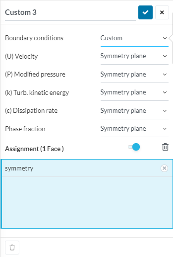
@pfernandez, has pointed out, in a below post, that symmetry conditions for CFD simulations can also be specified with the Custom>SymmetryCondition BC. However I do not see any parameter in there that indicates the ‘Slip’ condition that is applied to the selected selected faces when using this Custom BC, I will investigate that and report back here…
EDIT: Please Note that for best results, the face which you consider to be your symmetry face, MUST be PLANAR as pointed out by @pfernandez …
The symmetry plane you are pointing to refers to solid mechanics. Within SimScale, for CFD we have only the option to select symmetry, unless we go for a Custom boundary condition, were we can assign symmetryPlane for the different variables.
As far as I know, the symmetryPlane boundary condition inherits from symmetry and checks that the normals of all faces at the boundary point in the same direction, raising an error such as the following one when that’s not the case:
--> FOAM FATAL ERROR:
Symmetry plane 'ZQ1' is not planar.
At local face at (593.86 -7.37678e-07 149.954) the normal (-1.20113e-07 -1 -1.59815e-05) differs from the average normal (-1.42045e-11 -1 -1.88995e-09) by 2.55361e-10
Either split the patch into planar parts or use the symmetry patch type

    From function virtual void Foam::symmetryPlanePolyPatch::calcGeometry(Foam::PstreamBuffers&)
    in file meshes/polyMesh/polyPatches/constraint/symmetryPlane/symmetryPlanePolyPatch.C at line 64.

FOAM exiting
symmetry is more permissive and should give the same results as symmetryPlane when used with the same mesh.
Sorry, I missed that  (@jousefm Perhaps docs items could benefit from having the ‘Tree’ from where they are extracted, as shown as text on the screen and which would transfer with cut and paste operations )
In any case, a LOT of people use it for CFD symmetry and I think they do not realize that, if they do, it is nowadays only treated as a NO-slip wall.
I believe my simple Slip wall workaround for CFD is valid.
AND a big thank-you for introducing me to a much more customizable Custom>Symmetry boundary condition and for reminding me that I should point out that the symmetry face which is chosen, should be a planar face…
I will use it if I ever have the need to go beyond a simple Slip wall on a planar symmetry face.
EDIT: Doesn’t using a Slip wall force all normals to be aligned and have zero magnitude if the face is planar?
And effectively do the same thing as the Symmetry Condition that you described which does this:
In general, the symmetry condition applies the following constraints on the flow variables:
- The fluxes across a symmetry are zero.
- The normal components of velocity are set to zero.
- The normal components of all other variables are set to zero.
.
Did I miss something you were trying to get across to me ?
I decided to compare the results of a simulation using a Slip wall planar face as a pseudo ‘Symmetry Plane replacement’…
And the results of your suggested Custom>SymmetryCondition for u,p k,w (note this was incompressible CFD)
The good news is that they both converged almost identically and to virtually the same results…
So, unless I need to selectively un-select u,p,k or w on the Custion>SymmetryCondition tab, I will continue to use the simpler ‘Slip wall planar face’ to achieve proper symmetry for my results…
EDIT: I can also say that using a Symmetry Plane BC also provides virtually identical results as the above two methods and here is a link to that sim run…