simulation Static 9, geometry ламели 2
I’m getting an error when trying to generate a mesh.
simulation Static 9, geometry ламели 2
I’m getting an error when trying to generate a mesh.
The model was created in onshape
part studio 1 here
Hi @gkotelnytskyy!
I first thought that this might be related to the signs used for the name but when exporting your file to STEP the meshing works. However make sure that there are no intersections and overlaps in your geometry (see picture below).
Best,
Jousef
I’ve now updated the model - same document, simulation “Static 20”,
and now when I tried generating a mesh - it failed with " coarse"setting
now with “moderate” fineness - it’s been running for 26 core hours, and still is at 50%
What seems to be the problem now, and how is it to be fixed?
Hi @gkotelnytskyy,
I took a quick look at your model and I see several issues that could be causing the mesh generation issue.
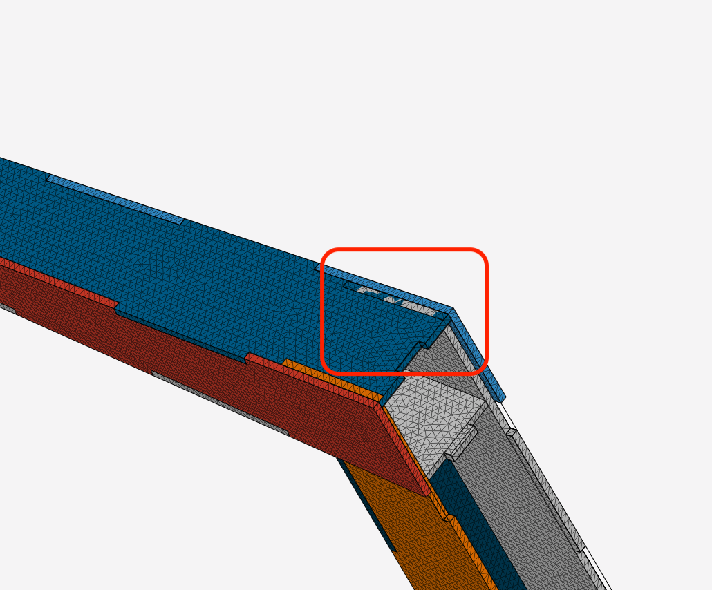
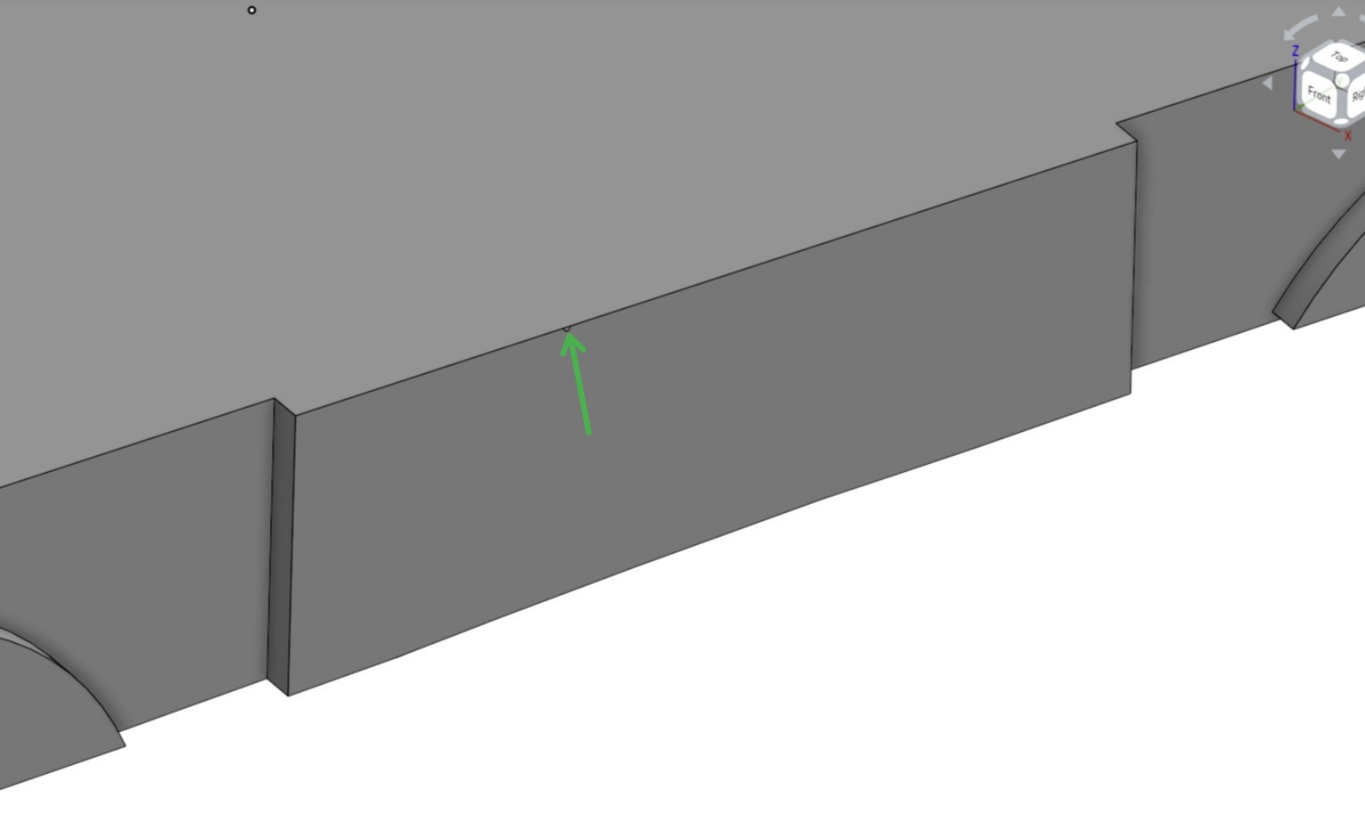
First, I removed the large freeeform slab, and then I cleaned up the geometry on the remaining parts. In the first image of your original geometry you have a lot of small surfaces. It seems like every time you created an extrude you ended up with a slight mis-match with the existing geometry. These small sliver surfaces and offsets will really drive up the meshing time and in most cases cause an eventual failure in the mesh.
The image below shows the same area as your original cad but all of the small surfaces were removed.
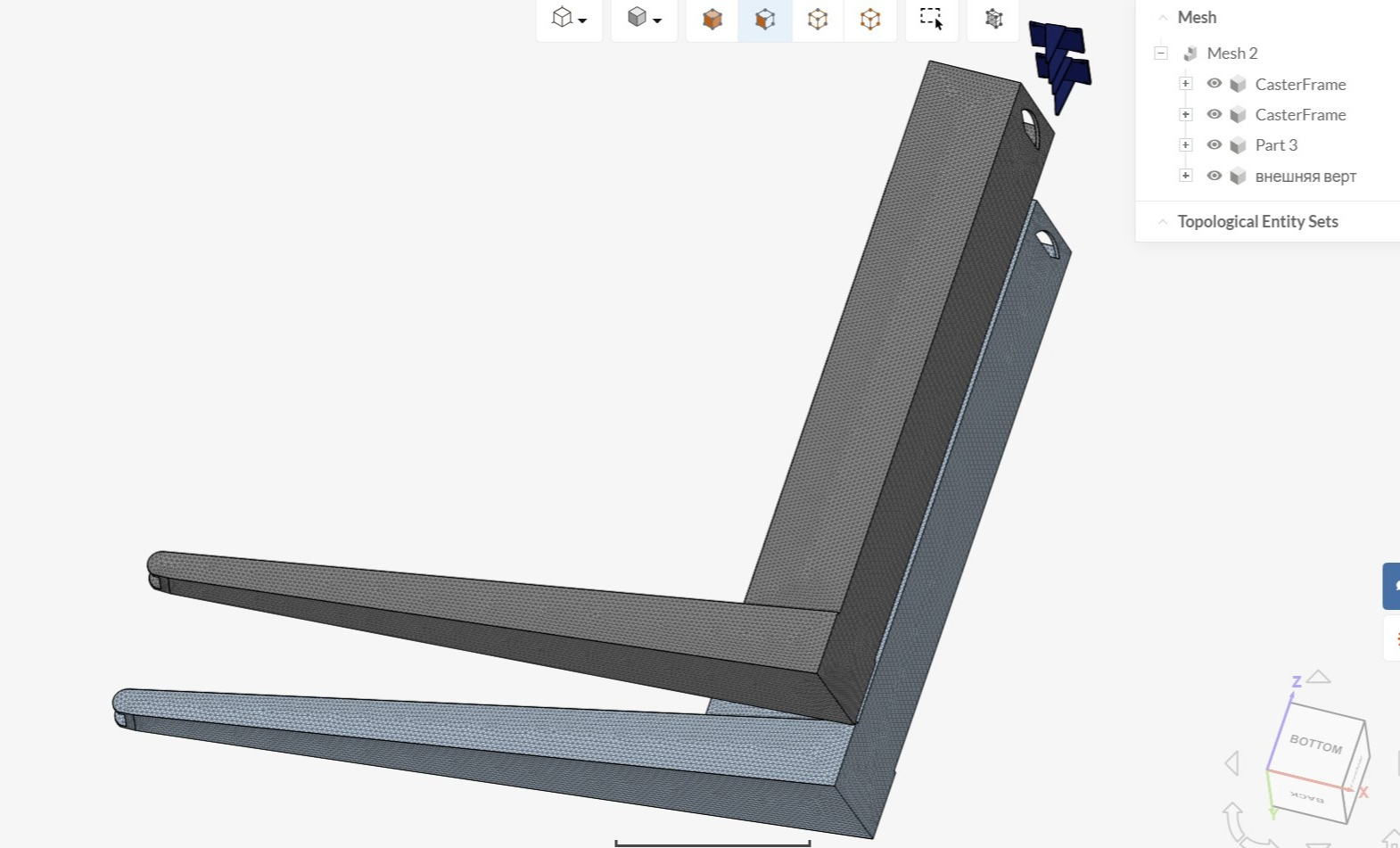
You can see in the mage below that these parts have a good mesh and it took 4 minutes to mesh. I did move the parts so I could easily see each part.
When I try to directly import just the freeform slab I get an error message in Simscale.
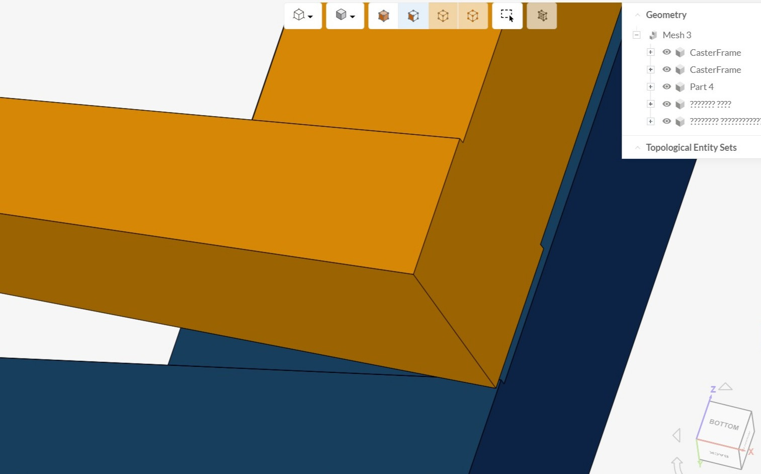
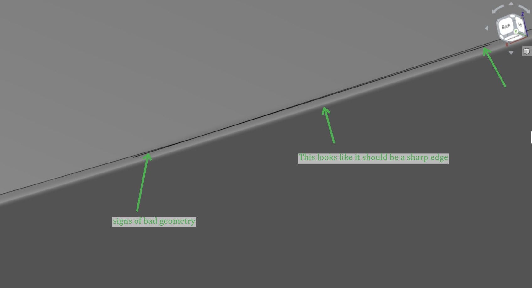
When I investigate the freeform slab in Onshape I am seeing several issues with the Geometry. Below are a few samples that will cause the mesher to take a long time and most likely fail.
If you can clean up and simplify your geometry it will make the meshing more successful and also yield better simulation results.
Please let me know if I can help any further.
Good Luck ![]()
Christopher
Thanks.
What’s practical way of simplifying the geometry? I’m working in Onshape,
the small protruding parts are “by design” - they come from sheets not being perpendicular.
Is there a way to automatically fillet them for the sake of modelling?
Hi @gkotelnytskyy!
Maybe trivial here but you can enforce perpendicular conditions inside of Onshape, already tried that?
Cheers,
Jousef
Hi @gkotelnytskyy,
Typically in FEA its good practice to remove any small features that will not be relevant to the the analysis. This usually means the design cad is not the same as the FEA cad. In your example I used Onshape’s Replace Surface command. I went through one at a time and replaced the small/angular surfaces with the larger planer surface next to them. With Onshape you might be able to manage these changes with Branching or Configurations.
Most of the issues I recall are caused by extruding a part into another part or to the rear wall of the other part. When you used the Boolean command to join the parts together you ended up with the geometry issues. A better option is to extrude the part up to the front face (or offset from the front face) so the the parts touch but do not intersect. If you are welding sheet metal together you might design the parts with a small gap between them. If you use this approach then that gap will need to be filled before importing into Simscale.
I hope some of this helps.
Christopher