Hi everyone,
I am designing an air inlet for the measurement cell of a portable fluorescence sensor and need help understanding an unexpected flow distribution in SimScale.
Project link: https://www.simscale.com/workbench/?pid=8168537471373415552
Physical setup
A pump draws air out through the outlet at the bottom of the measurement cell. Air enters through two paths:
-
A sample inlet carrying aerosol-containing air.
-
A sheath-air inlet supplying filtered air, intended to surround the sample stream and reduce recirculation in the measurement region.
At a measured total outlet flow rate of 0.81 L/min, the experimentally determined flow split is approximately 0.30 L/min sample flow and 0.51 L/min sheath flow.
I also visualise the flow using a light-scattering tracer aerosol and video recordings. These show the intended sample stream surrounded by the sheath flow.
SimScale setup
I selected Incompressible because the air velocities are comparatively low and I expect compressibility effects to be negligible.
-
Fluid: Air
-
Bottom outlet: Velocity outlet → Flow rate → Volumetric flow rate = 0.81 L/min, directed out of the domain
-
Sample inlet: Pressure inlet → Total pressure = 0 Pa
-
Sheath-air inlet: Pressure inlet → Total pressure = 0 Pa
Both inlet pressures are set to 0 Pa to represent air drawn from the same ambient environment. In the physical setup, the sheath air passes through a filter.
Unexpected behaviour
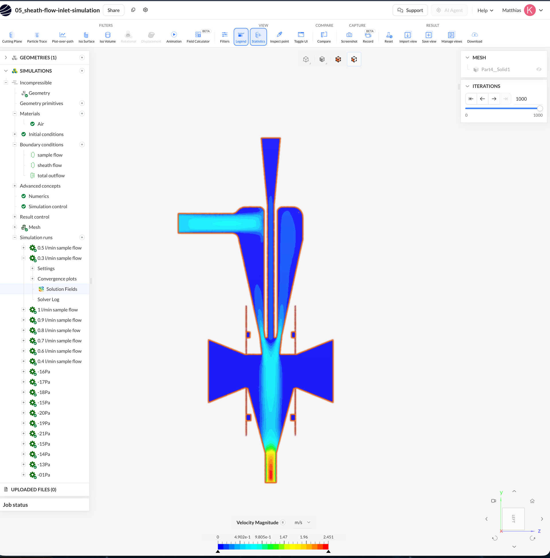
With both inlet total pressures at 0 Pa, the velocity-magnitude results suggest almost no flow through the sample path: its velocity approaches 0 m/s. This disagrees with the experimental observations.
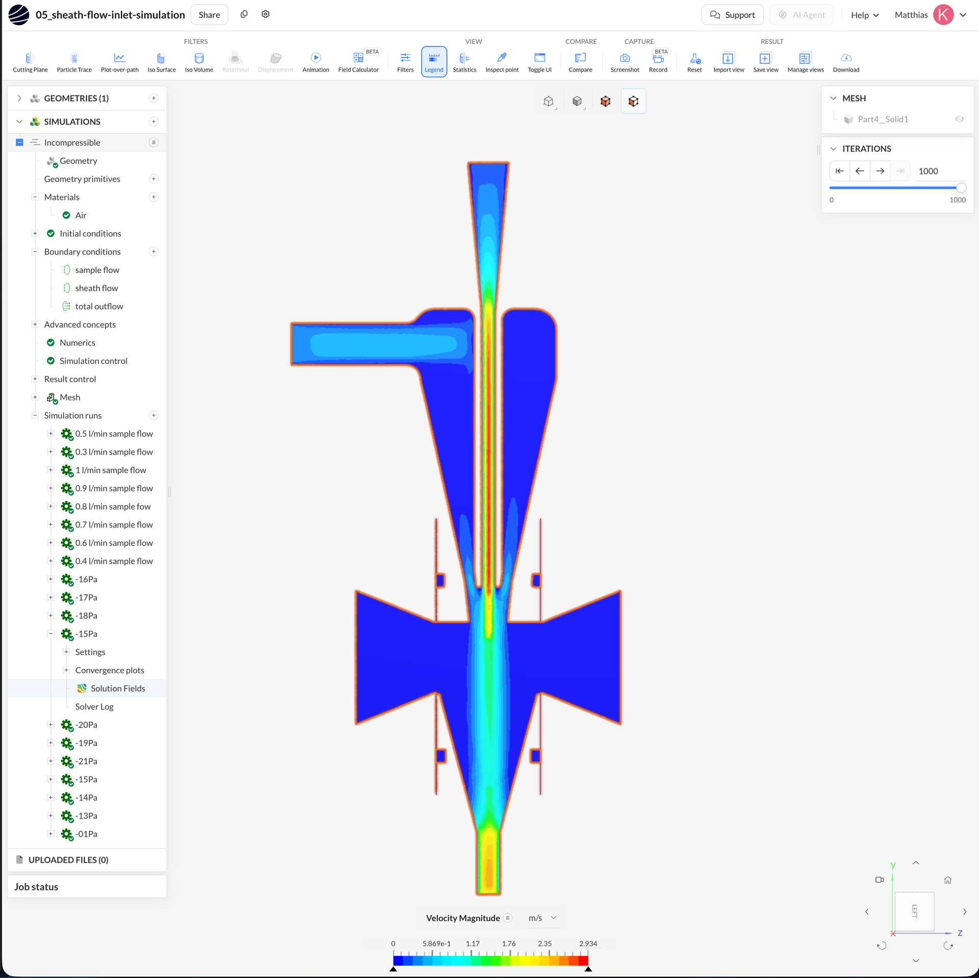
If I change only the sheath-inlet total pressure to −15 Pa, keeping the sample inlet at 0 Pa and the outlet flow at 0.81 L/min, a sample stream becomes visible. The velocity pattern then looks much closer to what I observe experimentally.
I tried −15 Pa to investigate the effect of the inlet pressure; this value was not obtained from a pressure measurement.
Are these boundary conditions appropriate for representing the suction-driven setup, and what could explain why lowering the sheath-inlet pressure is necessary to obtain a flow pattern resembling the experiment?
I am attaching velocity-magnitude screenshots for comparison:
-
Case A: Both inlets at 0 Pa.
-
Case B: Sample inlet at 0 Pa, sheath inlet at −15 Pa.
Both cases use an outlet flow rate of 0.81 L/min.
Thank you for your help,
Best regards,
Matthias