
Hi everyone,
I am working on a Data Center simulation (Conjugate Heat Transfer - CHT) using SimScale, and I am facing a recurring error related to material assignment and solid bodies. I would appreciate some guidance on my workflow.
My Workflow & The Problem:
I imported a volume from Revit that represents my airflow domain (the room). Note: This volume is hollow inside.
Because I needed to define specific areas as “cabinet doors” (inlets/outlets), I performed an ‘Extrusion’ to create these volumes and then a ‘Subtract’ operation to integrate them into the main volume.
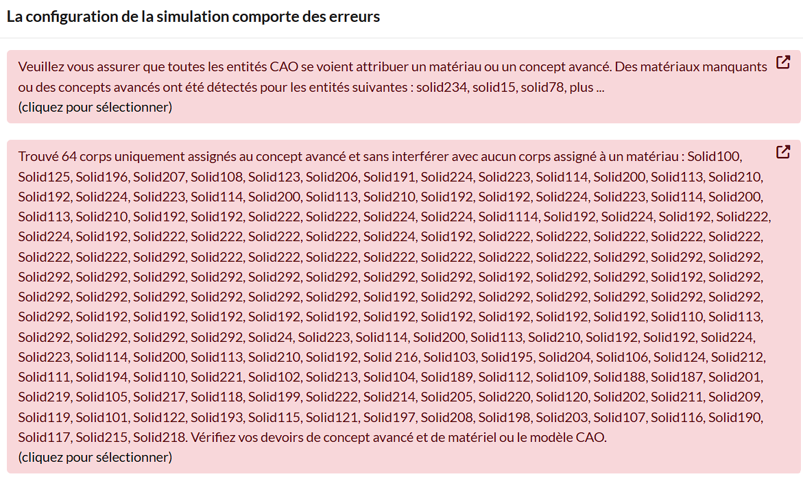
The Issue: Since I performed the ‘Subtract’ operation, the software now views these doors and the main volume as a single, complex solid body. It forces me to assign a physical material to all these parts, but these are meant to be airflow interfaces, not solid parts. If I don’t assign a material, the software blocks me from proceeding.
Questions Regarding Power Sources:
4. For the server heat loads (Power Sources), I am unsure how to represent them correctly. Should I draw a small “box” inside the flow volume to represent each server? If so, how should this box be defined within the flow region without creating the same solid body conflict I am currently experiencing?
What I have tried:
I have been advised to use ‘Delete Body’ in the CAD Edit mode, keeping only the flow region.
If I delete the solid bodies of the cabinets and doors, will the boundaries (the imprints) remain as selectable faces on the main flow volume?
What is the best practice to create “inlet/outlet” interfaces on a flow volume without adding solid bodies that trigger material assignment errors?
For my perforated plates (Porous Media), should I keep them as separate solids and leave them as ‘Unassigned’ in the material list?
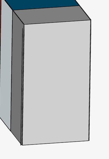
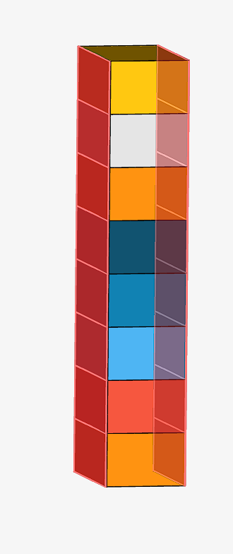
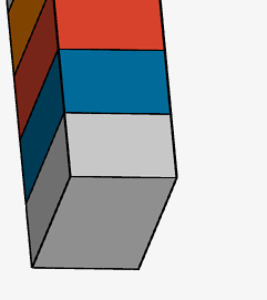
I have attached a sketch of my geometry (“1000406318.jpg”) and a screenshot of the material error (“1000406317.jpg”). Any advice on the correct CAD-to-Simulation workflow would be highly appreciated.
Hi @souhail_achand,
Welcome to the forum! The issue you are facing is actually a very common hurdle when bringing architectural models (like Revit) into CFD.
The core of the problem comes down to the difference between modeling a physical room versus modeling the fluid domain. In a CHT simulation, your CAD model should not be a “hollow room.” Instead, it needs to be a solid block that represents the air itself.
Here is the breakdown of how to fix your workflow and answer your specific questions:
1. Creating Inlets/Outlets (The “Solid Body” Error) You do not need 3D volumes or solid bodies to represent cabinet doors or inlets/outlets. An inlet is simply a boundary condition applied to a 2D surface.
- The Fix: Instead of extruding and subtracting, you should use the Split Face tool in CAD Edit Mode (or your local CAD software). You simply draw the outline of the cabinet door on the outer boundary of your main air volume and split that specific face. This gives you a selectable face for your inlet/outlet boundary condition without creating any new solid bodies to trigger material errors.
2. Representing Server Heat Loads (Power Sources) You have two options here, depending on how detailed you want to be:
-
Surface Heat Flux (No solid body): If you don’t care about conduction through the server chassis, you can subtract a box representing the server from your main air volume (creating a void). You then apply a “Surface Heat Flux” boundary condition to the faces of that void.
-
Volumetric Heat Source (Requires a solid body): If you want true CHT, you must have a solid box representing the server inside the air domain. You will assign a physical solid material (e.g., Aluminum) to this box, and your air volume must be perfectly imprinted against it. You then assign an “Absolute Power Source” (under Advanced Concepts) to the volume of that solid box.
3. Perforated Plates (Porous Media) Yes, you must keep porous media as separate, distinct solid bodies (volumes) within your CAD model.
- The Workflow: Do not assign a solid material (like steel) to them. Instead, you assign your fluid material (Air) to these volumes. Then, under Advanced Concepts, you assign a Porous Medium to those specific volumes, which tells the solver to apply a pressure drop across that region of the air.
4. The ‘Delete Body’ Question If you use a tool body to imprint or split a face on your main flow volume and then delete the tool body, yes, the split faces (the imprints) will remain selectable on the main volume. However, using the dedicated “Split Face” operation is usually much cleaner and less prone to boolean errors than creating and deleting entire bodies.
Summary of Best Practice: Your flow volume should be one continuous solid block of air. Use Split Face for 2D boundaries (inlets/outlets) and only use separate solid bodies for regions that require a volumetric definition (like solid servers for CHT or Porous Media).
Hope this helps clear up the workflow! Let me know if you hit any snags in CAD Edit mode.
Hi @souhail_achand,
Just to add one small clarification to the response above:
-
Porous regions do not need to be modeled as solid parts with material properties. They can instead be defined using geometry primitives or cell zones within the fluid domain.
-
However, porous media in SimScale is used to represent the pressure drop / flow resistance through the region. It does not model solid heat conduction or detailed thermal behavior.
-
If you need to resolve conduction through the object itself, then it should be represented as a solid body with an appropriate material.
So in general, keep solid bodies where the solid thermal behavior matters, and use primitives or cell zones for simplified porous or source regions.
Thanks,
Bryan