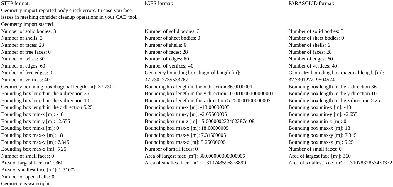
I have imported the geometry for a conjugate multiphase flow-heat exchange simulation project and found that only the STEP file reported been watertight and having shells. But, this STEP file reported having an error: “Geometry import reported body check errors. In case you face issues in meshing consider cleanup operations in your CAD tool”. I don’t know what this error might be.
On the other hand, the IGES and PARASOLID didn’t report errors but didn’t report watertight feature and shell presence neither.
To do the meshing and simulation, which format should I choose?
I attach an image of the data of event log for the 3 formats.
You may still continue the meshing process though even it the message appears - please use the new mesh preview! Please also share your geometry (project link) with us to see if the CAD itself has some issues. If the CAD itself is broken in the first place you would have to check that first.
Mr. Jousefm
Thank you for your quick response.
Here is the link to the project:
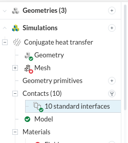
The CAD format that I’m starting to work on is the 3rd one, the one in Parasolid format. I already added topology assignments so it can be better understood. I think this CAD is good because the fact of having the 3 solid bodies I need means they are watertight. Additionally, when I jumped in to the simulation stage, it automatically matched the contact faces which will be the interfaces for heat transfer.
I hope you can confirm if my CAD model is fine enough to continue to the meshing stage.
In the project you have shared, the geometry is not meshed so we do not have the benefit of seeing the mesh log. My guess is that you either have intersecting parts or lack of contact between parts. Could you perhaps simplify your CAD model by altering the cylinders so that they have flat ends? You have not told us what you are simulating so I can’t say if this is a reasonable simplification to make, but if you can do this then it can only help. Also, use your CAD package to check for interference. and that the parts are properly assembled.
Hi roy_g, and thank you for your response.
Yes, the mesh is not generated yet. At the moment, I’m trying to find out which of the CAD format is convenient to mesh.
About the simulation, I’m trying to see the effect (on the LNG) of the heat leak from ambient to the tank while moving through the road. The Air volume will be air moving pass the tanker truck. The Insulation volume will be expanded perlite. The LNG volume will be Liquefied Natural Gas with a filling of about 85%, so it will be a multiphase conjugate simulation.
I’ve already checked the CAD and the matching faces for heat exchange exist. Furthermore, I see that Simscale meshing already recognized the contact faces.
I checked your all three format. your STEP AND PARASOLID format was good means there is no problem in this format but your igs have some problem. there was some overlapping or intersecting surface in your igs format. so, don’t use igs right now you can continue your meshing with other two formats.
Importantly, you don’t need to model all the parts in your CAD program. Model the cylinder walls only in CAD. Now under geometries (at the top of the menu), click on your geometry and select add geometry operation. Use ‘enclosure’ to add the air volume around the cylinder and use ‘closed inner region’ to add the gas volume inside the cylinder. There are tutorials on the website showing how to use these operations.
Extra tip, if you are not already doing so, build your cylinder in your CAD program in a single step using the revolve tool, this will help avoid problems.
I imported the CAD as it is because I already had it with volume and face assignments.
During the drawing of the CAD, I used revolve operations. By the way, I did the CAD in DesignModeler; and there, I did the volume and face extractions.
But next time I draw a CAD model, I’ll keep it in the main surfaces.