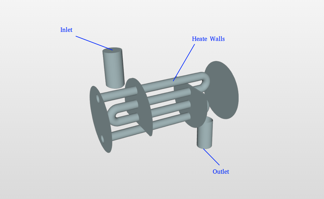
Geometry
For this tutorial we will use a heat exchanger geometry [which can be found here]
In this geometry the hot fluid is moving inside the pipe so the pipe walls are assumed to be at fluid temperature. The pipe is surrounded by air domain with single inlet, single outlet for air.
Mesh
Select the geometry and then click on New Mesh. A new mesh setup will be created instantly
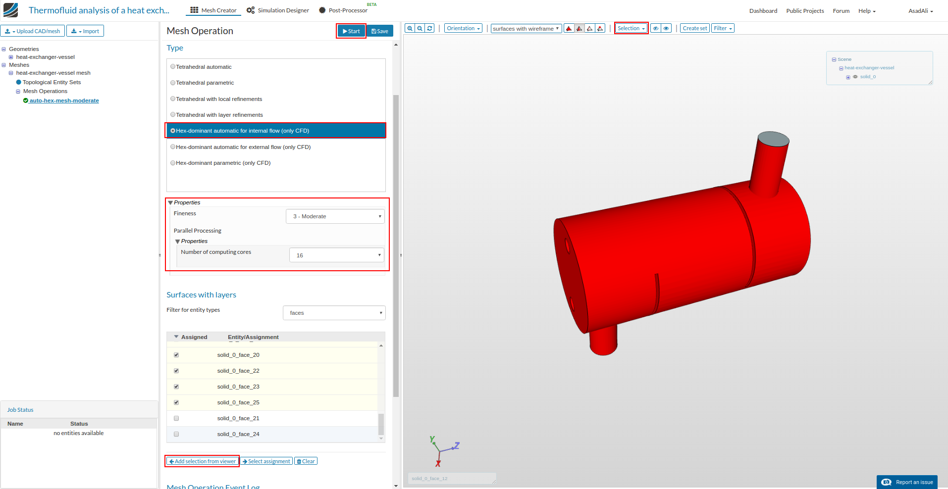
Now select Hex-dominant automatic for internal flow (only CFD) set the fineness to “3- Moderate” in properties. Set the number of processors for this operation to 16.
To add the faces for layers addition, press the Selection in the viewer and click “Select all” to select the whole geometry. Now unselect the inlet and outlet face. Finally click Add from viewer and click Run to start meshing.
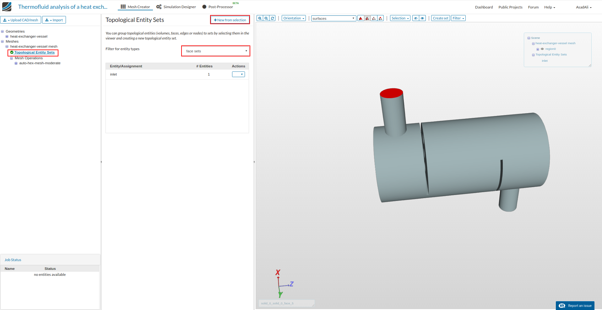
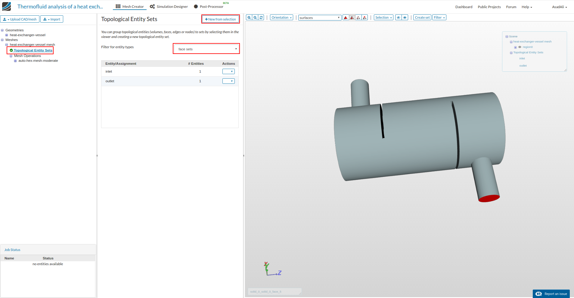
Once mesh is ready make face sets. Slick on Topological entiity set, select the inlet face and click New from selection, give the name “inlet” to this face and press “create” to make inlet face.
Similarly make outlet face set.
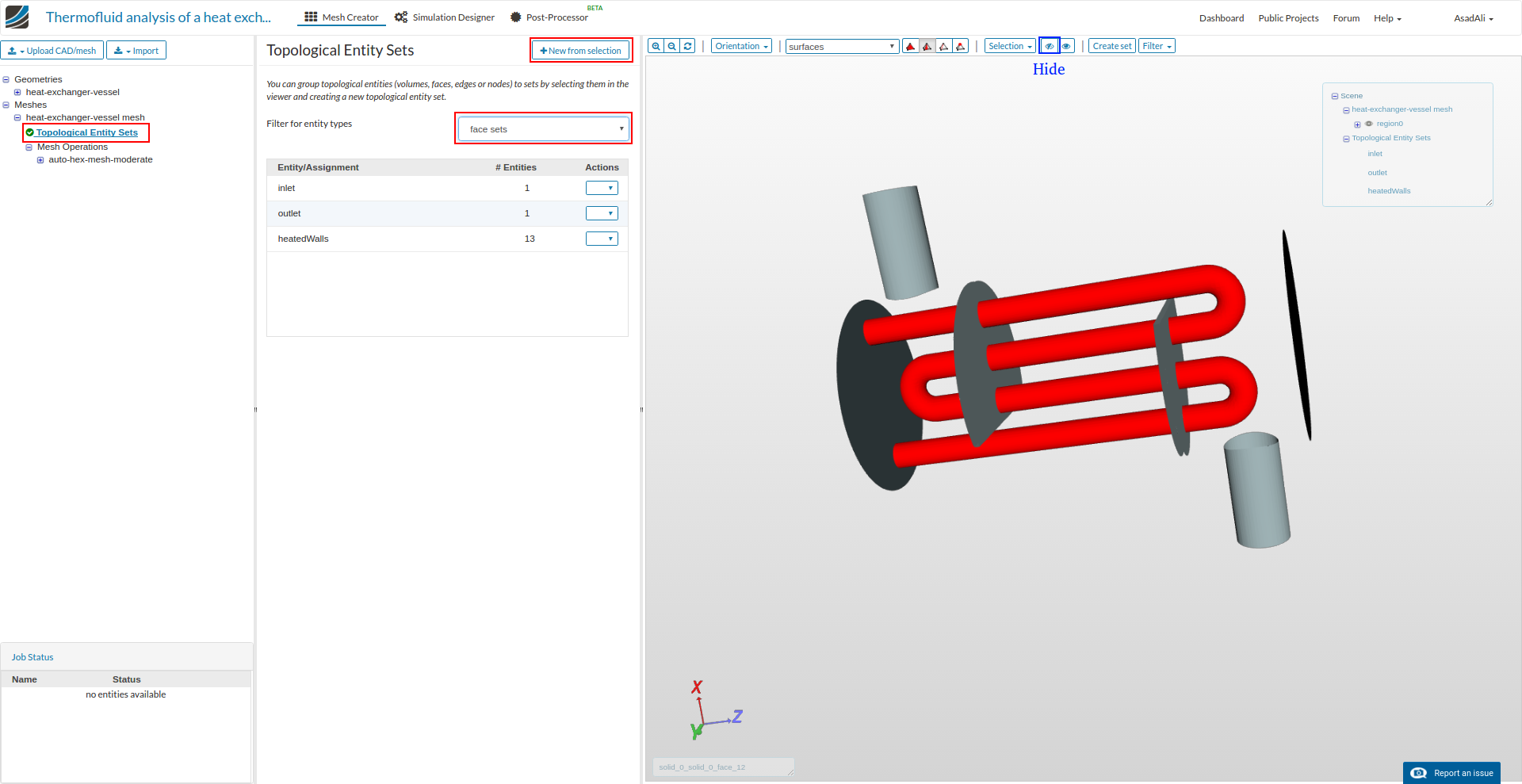
To make a set for heated walls, first hide the outer wall by click on the wall and pressing hide icon from the viewer. Now select the pipe walls and make the face set by the name “heatedWalls”.
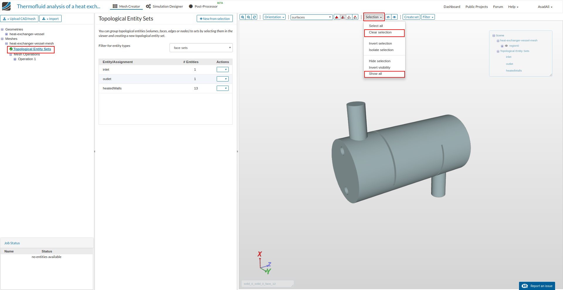
Finally make the face set from the remaining walls. First make sure that the no face is selected by pressing “Select all” from the viewer, and clicking “Clear selection” and “Show all”.
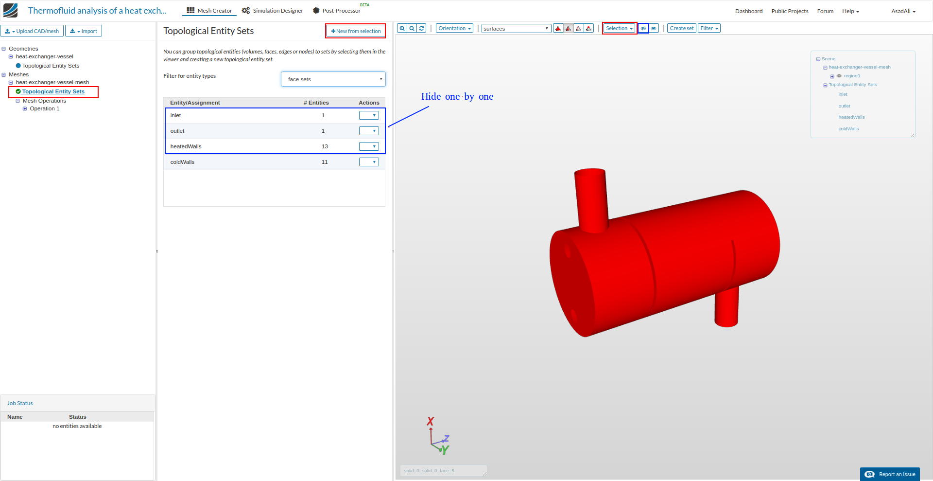
Now select inlet, outlet and heatedWalls face sets one by one and hide them. Finally select all from the viewer and make face set by the name “cooledWalls”.
Simulation
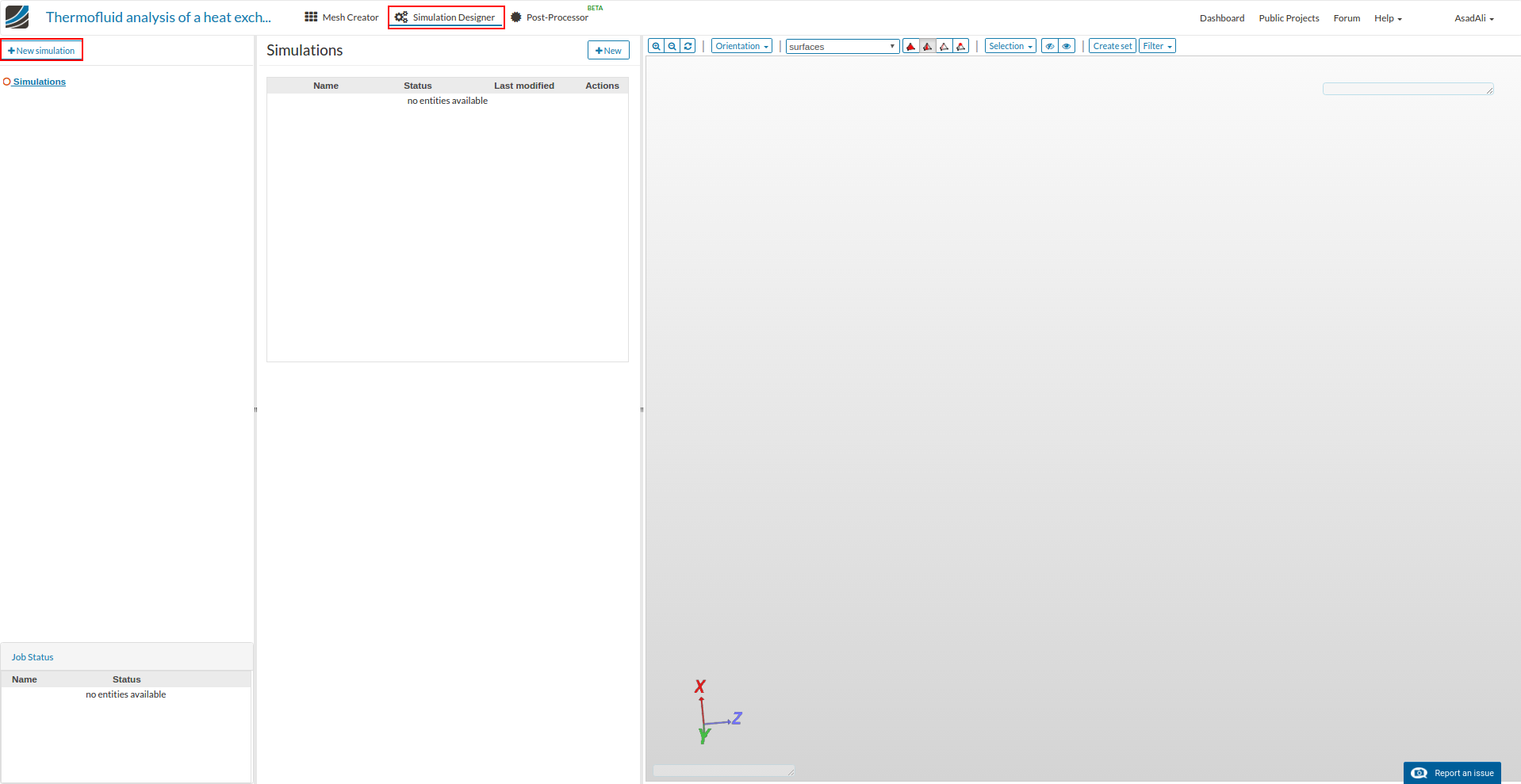
Move to the simulation mode by clicking Simulation Designer and click New simulation to create a new simulation setup.
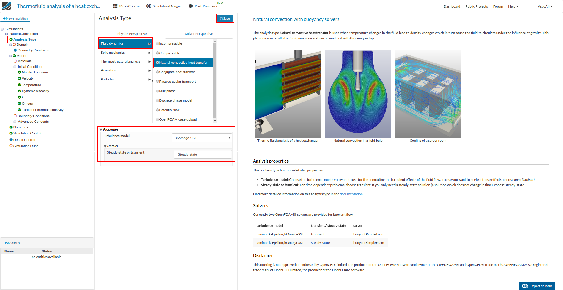
Once simulation setup is created, change analysis type to Fluid dynamics and Natural convection heat transfer. Set the properties to K-omega SST for turbulence model and Steady State.
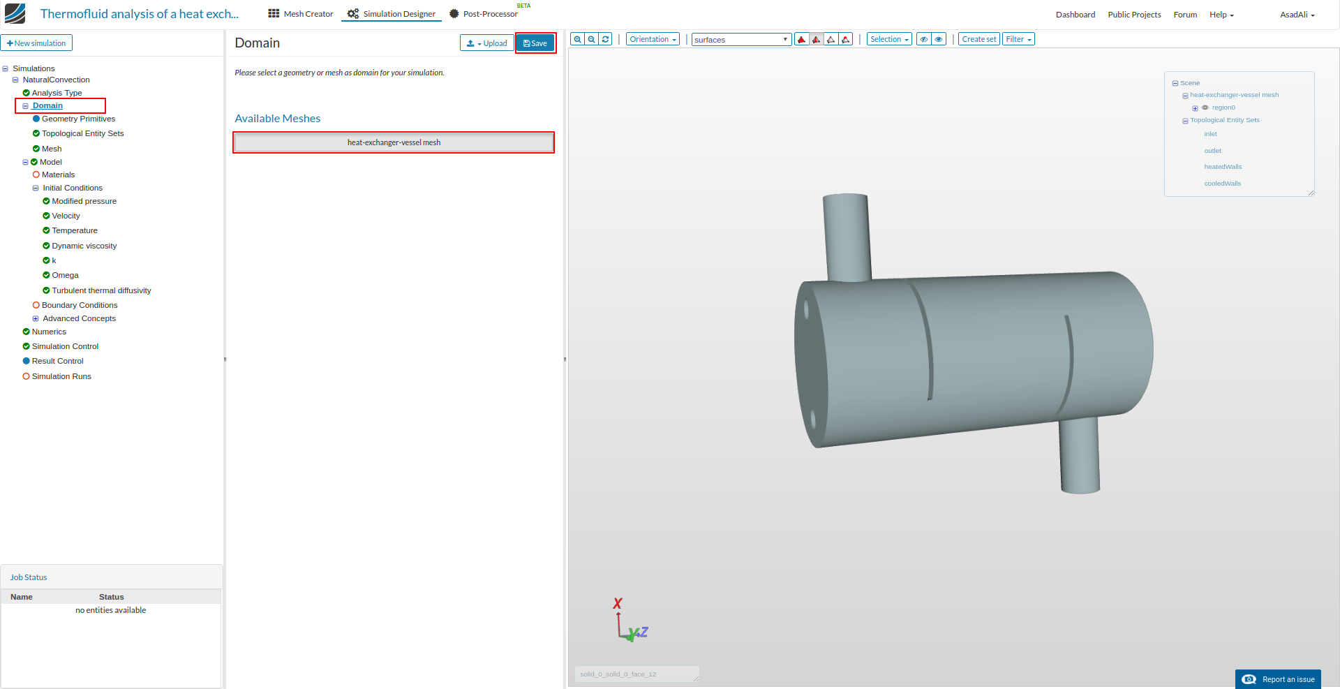
Now in simulation setup tree click on Domain, select mesh and click Save.
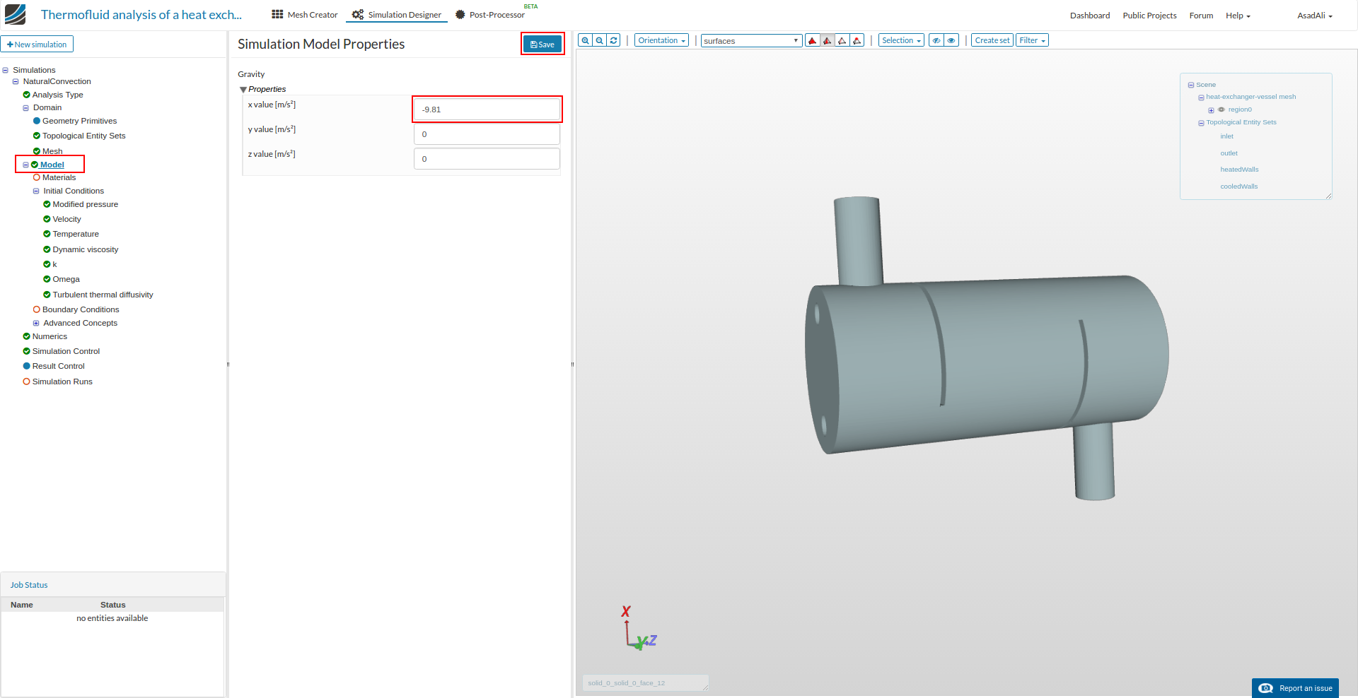
Move to Model and give gravity according to the orientation of the geometry, in this case along x-axis, and press Save.
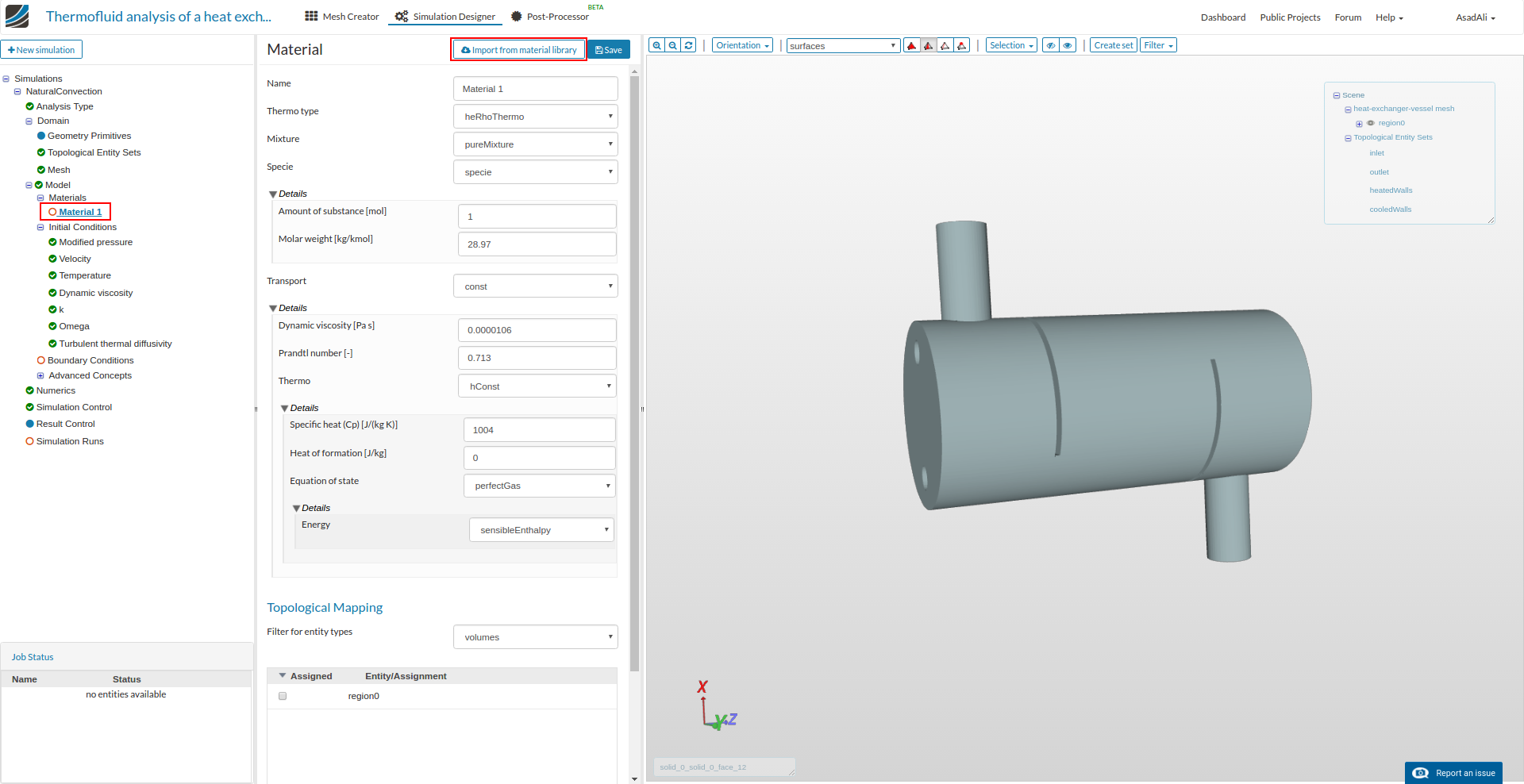
Now we have to assign materail to the domain. Move to the Material 1 and press Import from material library.
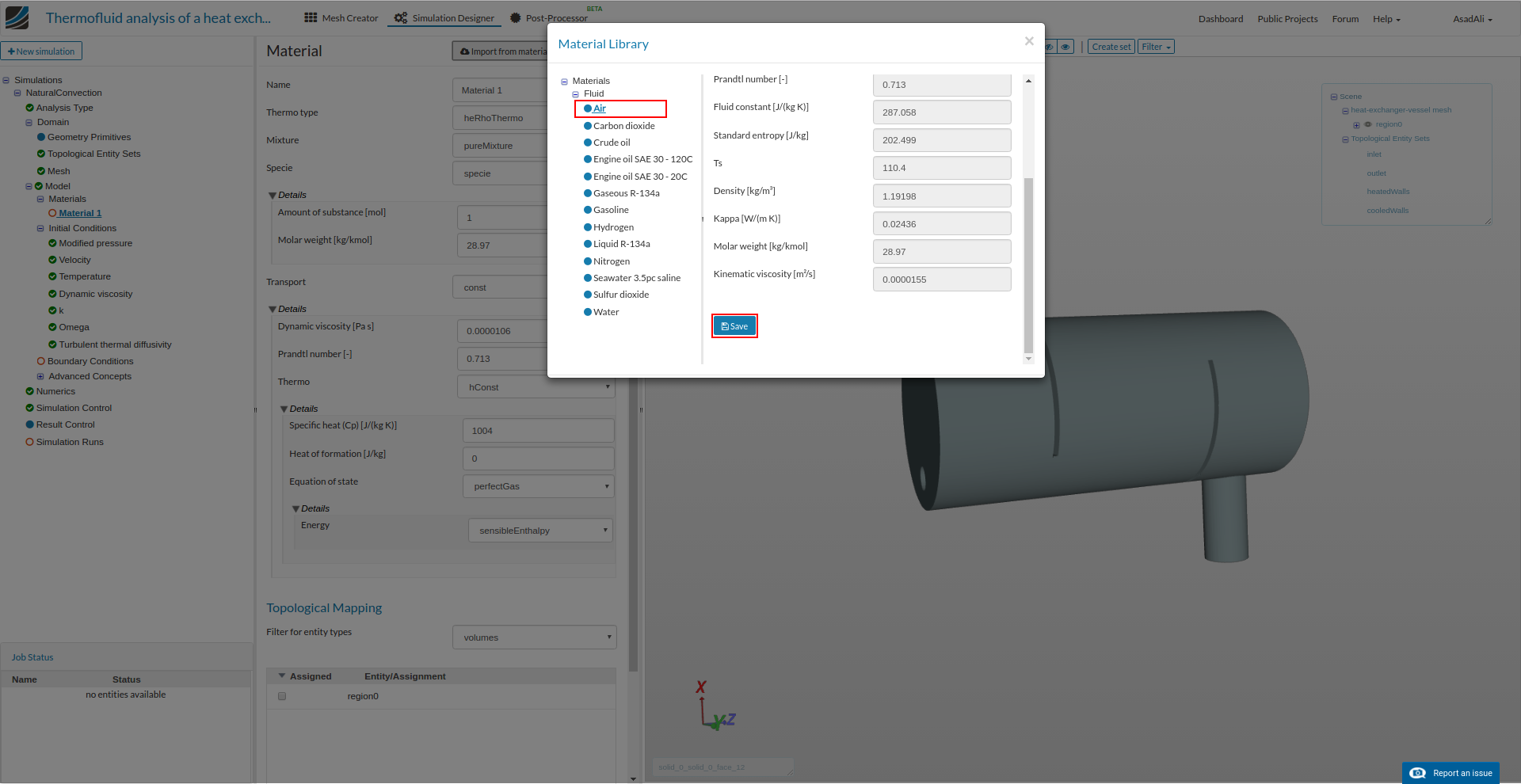
Select Air and press Save.
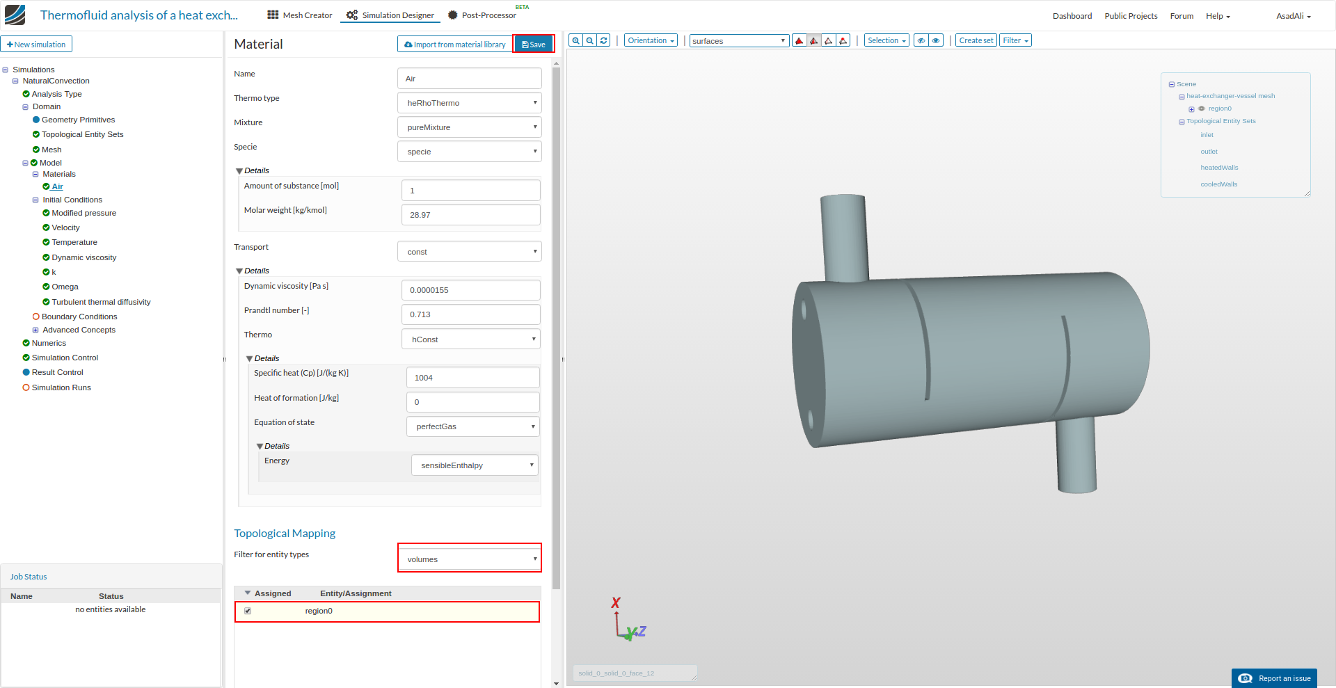
Now assign this material to the domain by checking region0.
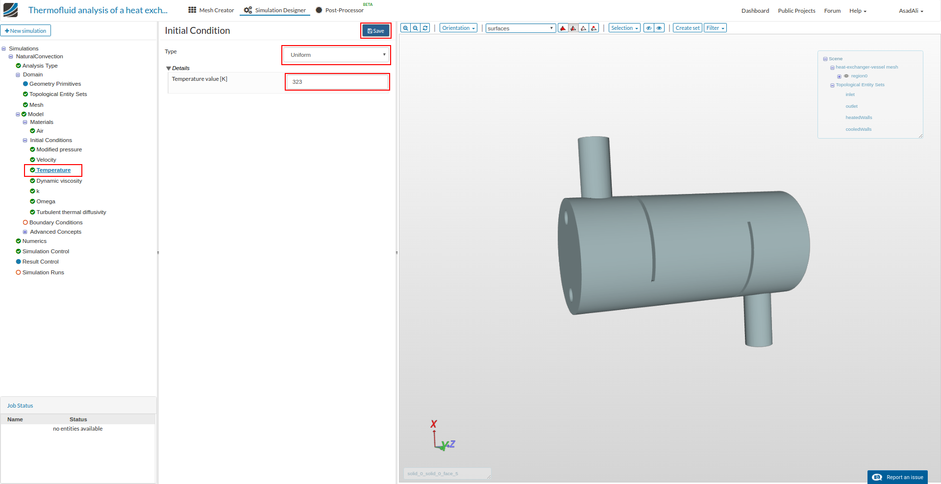
Now to set initial conditions, click on Velocity, set the initial velocity according to the image and Save.
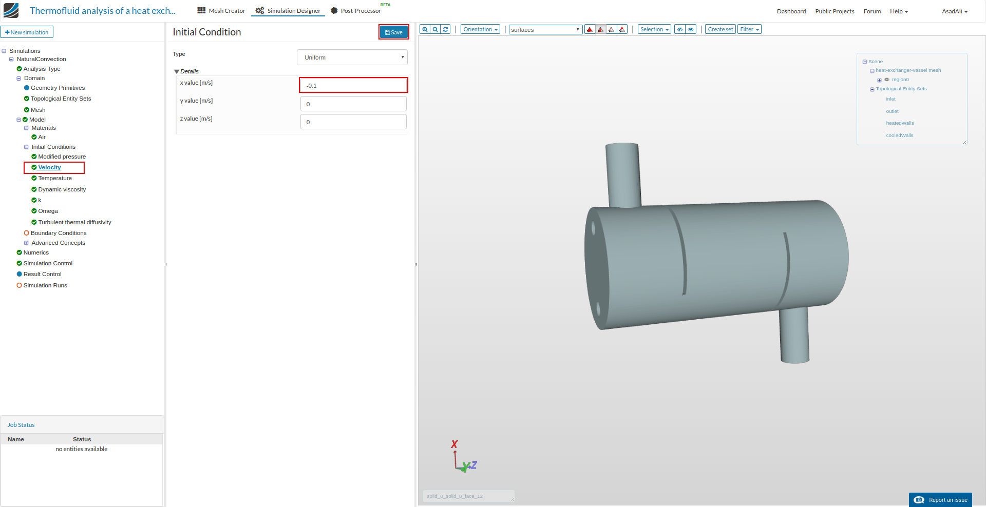
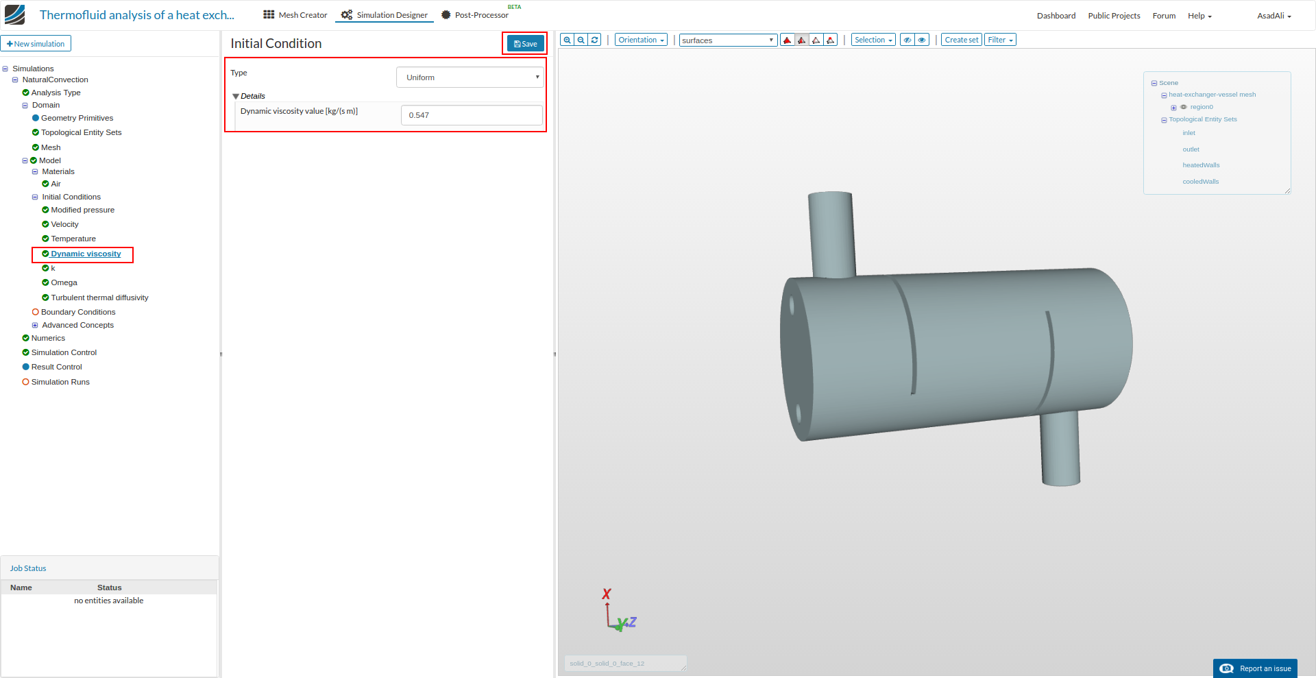
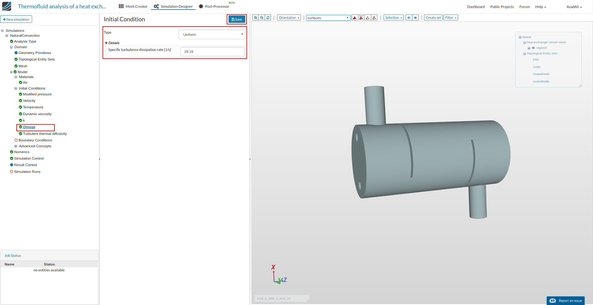
Similarly set the Temperature and other initial conditions accordingly. Use default values for the quantities which are not listed in images.

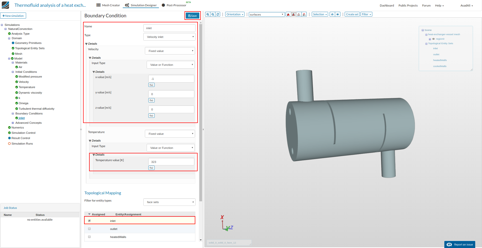
To set the boundary conditions move to Boundary Conditions, press New to add new boundary condition and name it to “inlet”.
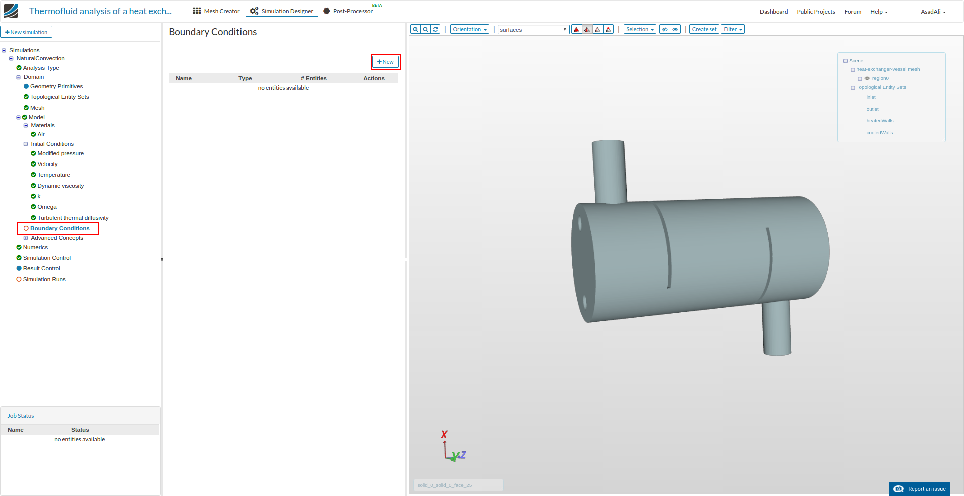
Set the parameters for the inlet boundary condition as in the image, assign the “inlet” face set to this boundary press Save.
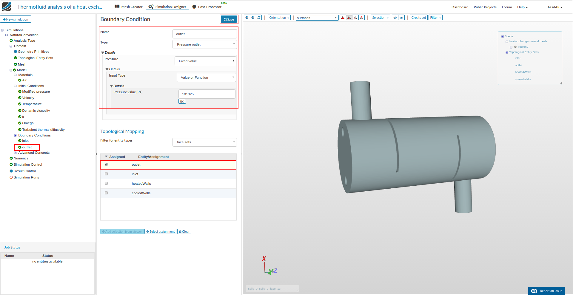
Similarly add another boundary condition for the outlet, assign the “outlet” face set, give the values as in the image and press Save.
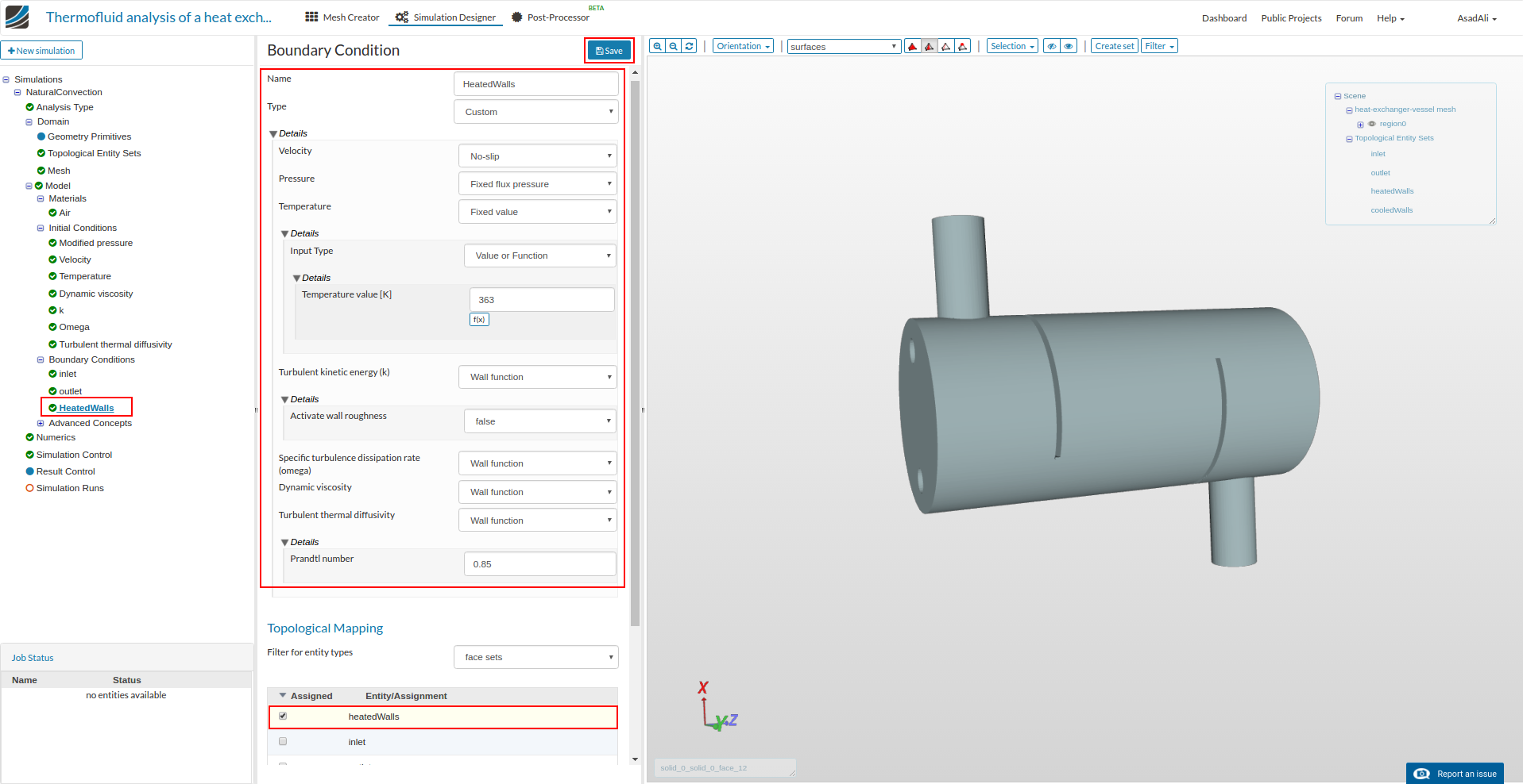
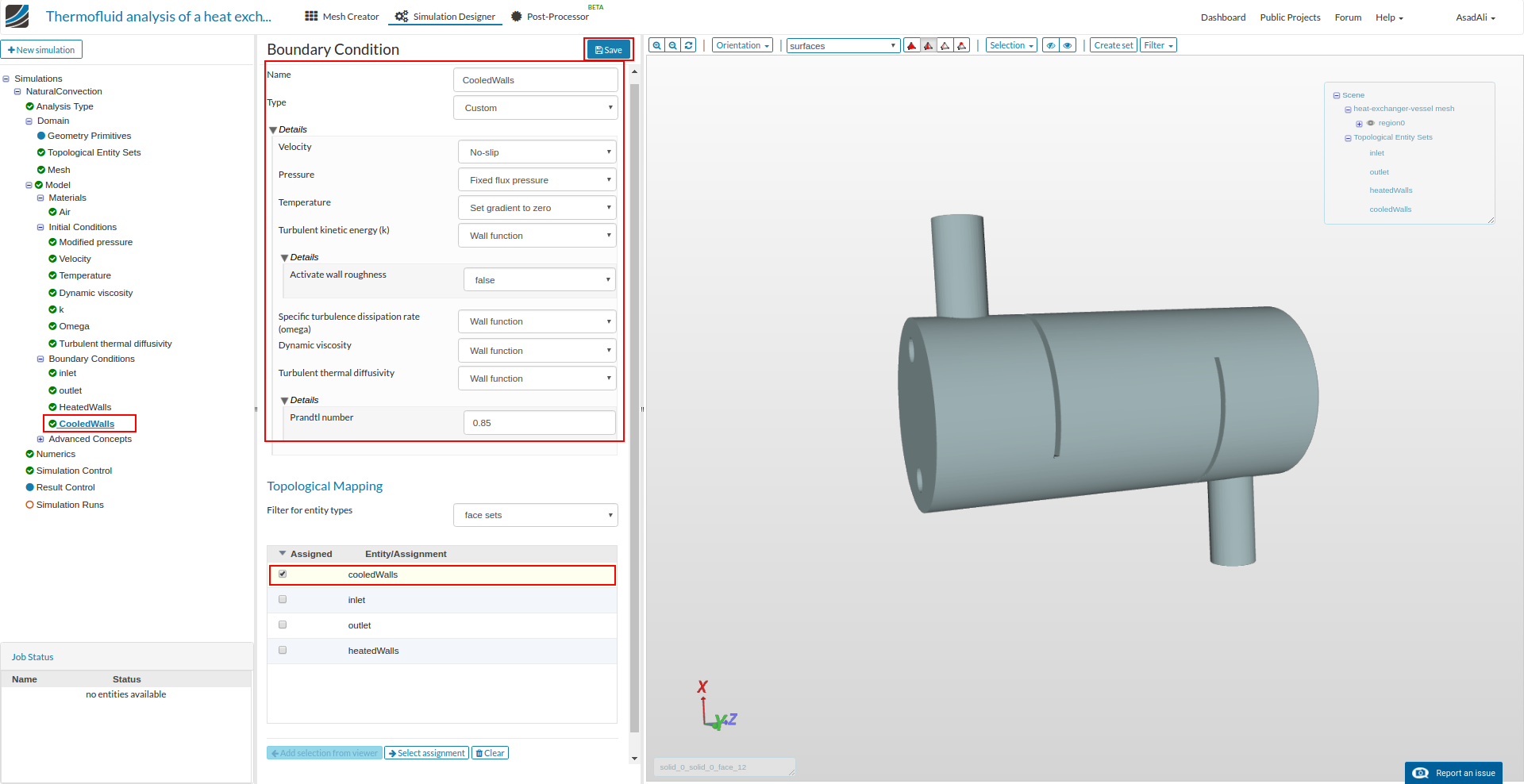
Similarly set the boundary conditions for heated and cooled walls and assign the respective face sets.
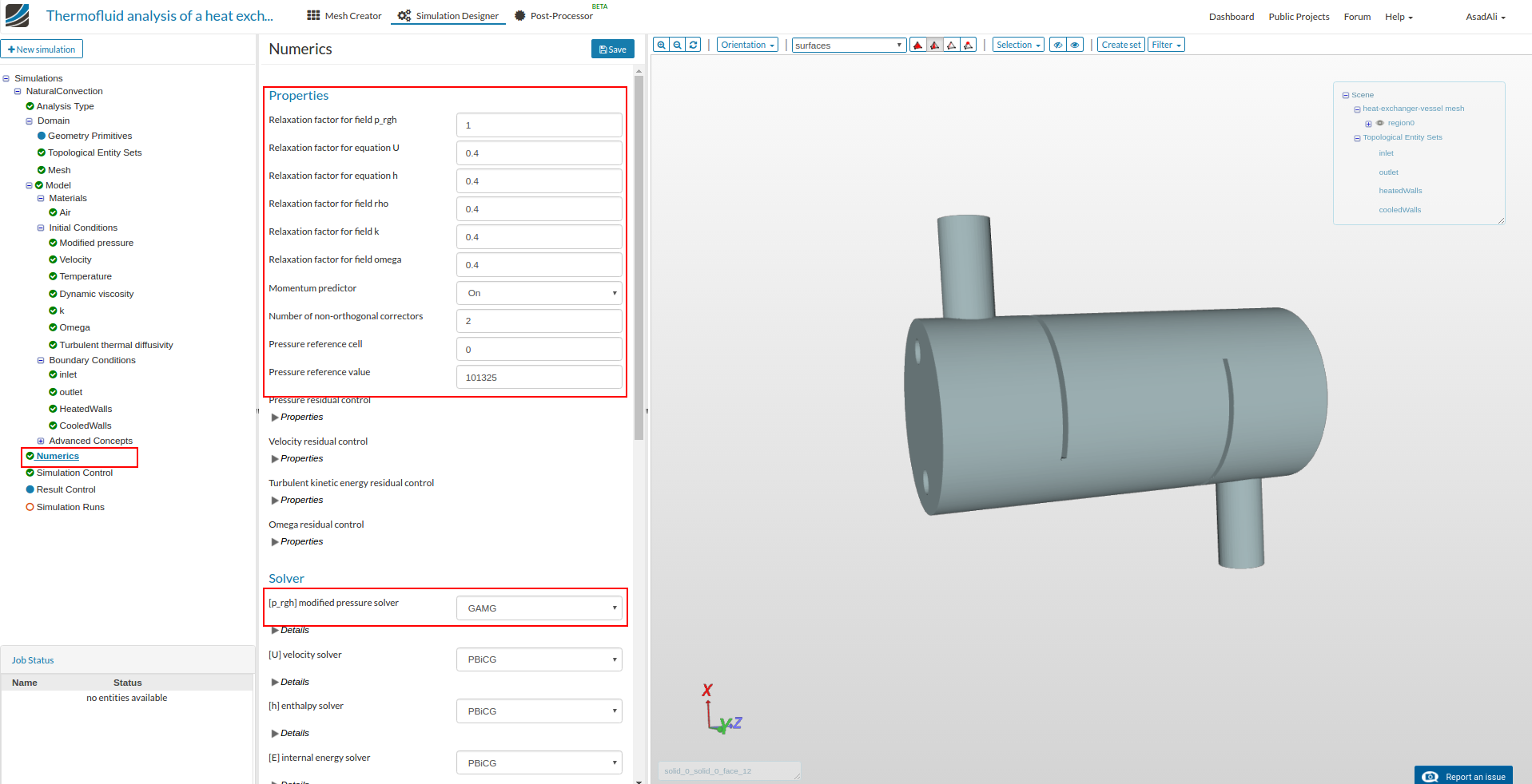
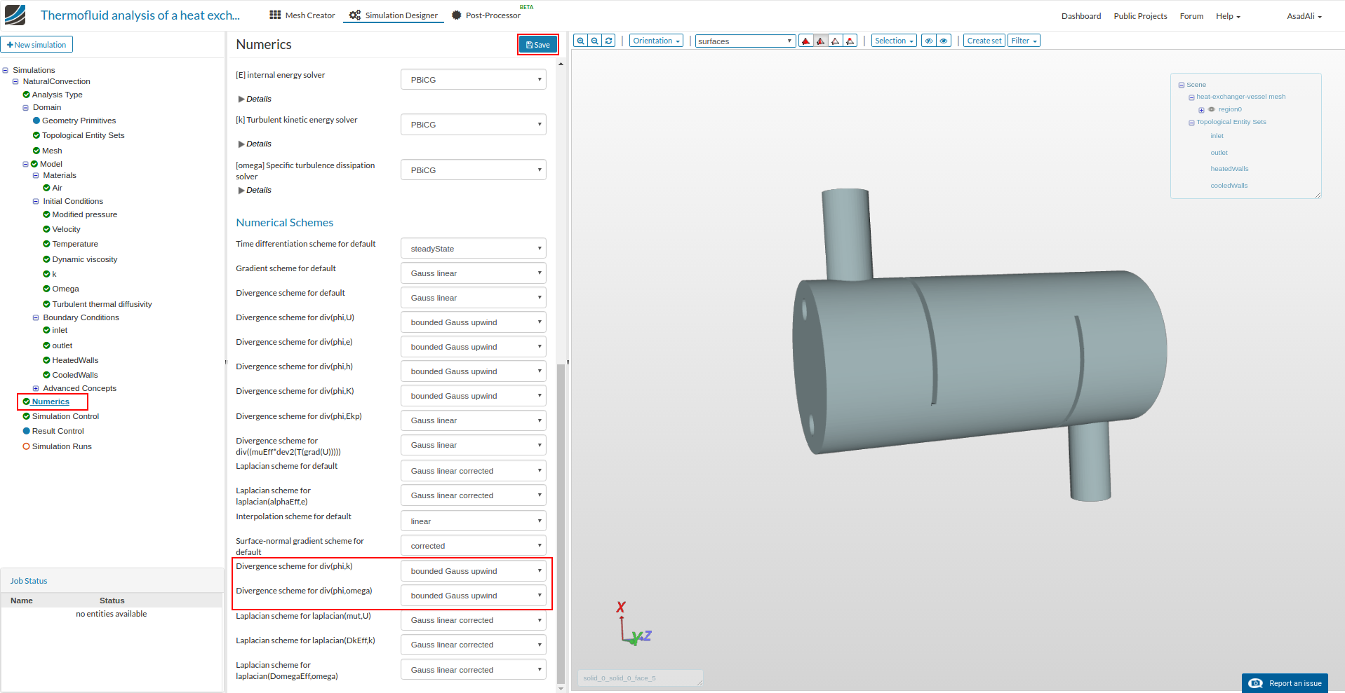
Now move to the Numerics and set the solver properties accordingly.
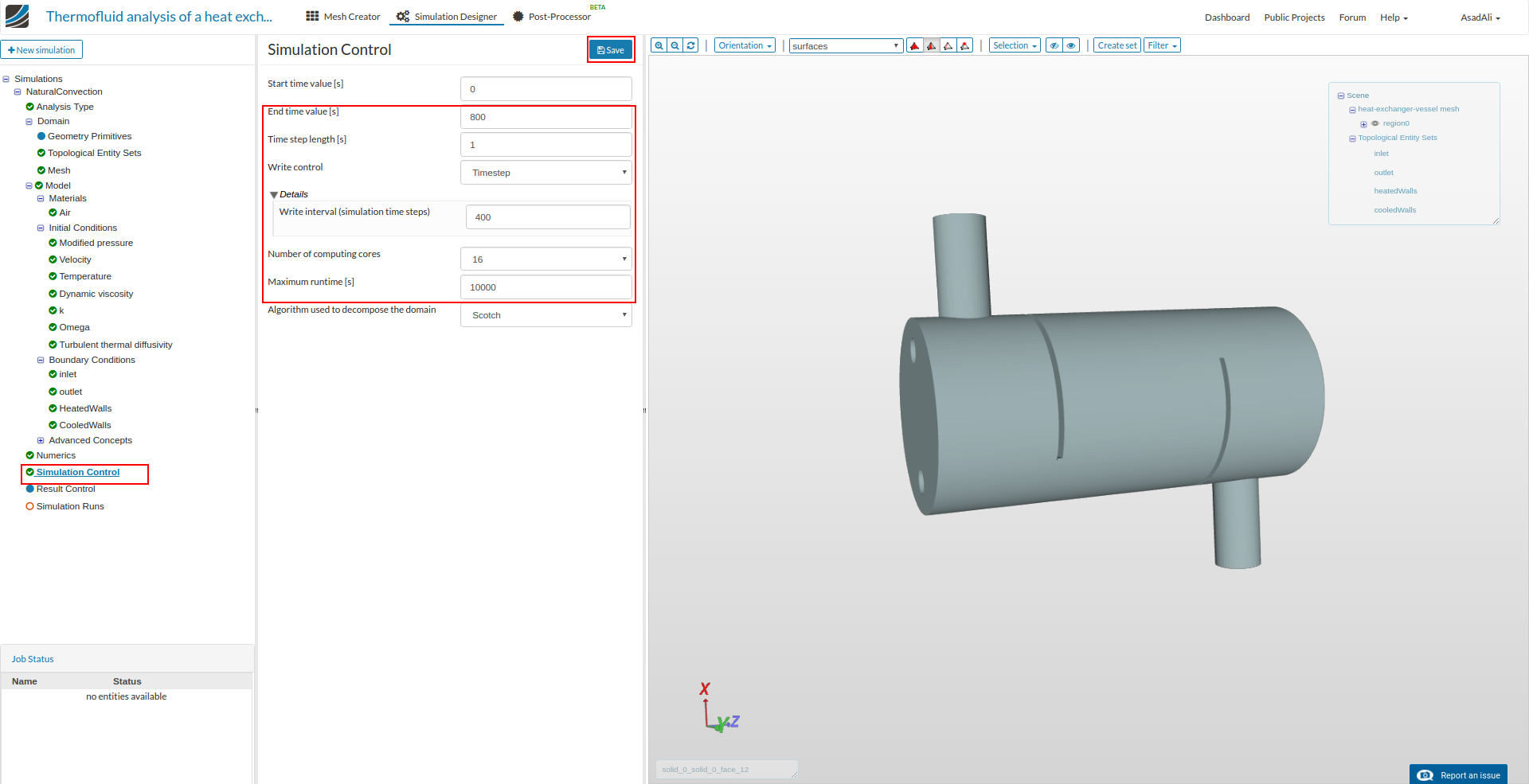
Now move to the Simulation Control and set the values accordingly.
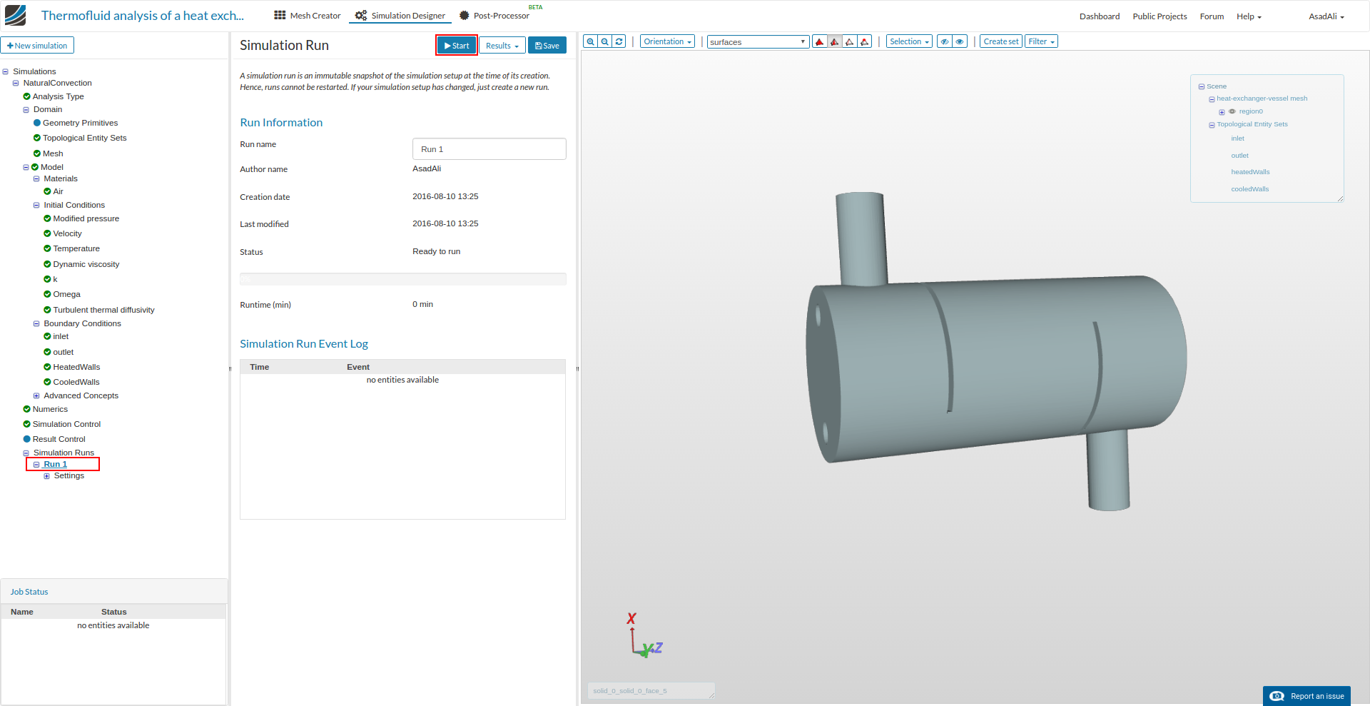
Finally move to the Simulation Runs and create new run. Press Start to start simulation.