@jousefm and @radenpm9 - Automatic snappyHex for internal flows was renamed to Hex-dominant automatic for internal flow (CFD). Thanks for pointing that out, I’ll update the tutorial to avoid confusion!
Hi @jousefm,
thanks for your reply. Then there is some difference between numerics in tutorial and yours. I uses yours (I think they are better anyway) and my simulation converged after about 200 minutes. In my first case I used the tutorial numerics and the convergence curve was very smooth, bur the convergence was too much slow.
One problem: the result of the first simulation is completed (I have the results) but there is an error (the bar is red!!)
you cannot say in general that mine is better (I would rather say that the options Milad choses are better because he has way more experience than I have). The approach to verify this “better or worse” issue would be a benchmark and see which simulation gives us the best results.
Concerning your error please try it with the simulation properties Milad has given in the description.
If you still cannot manage to finish your simulation contact me again.
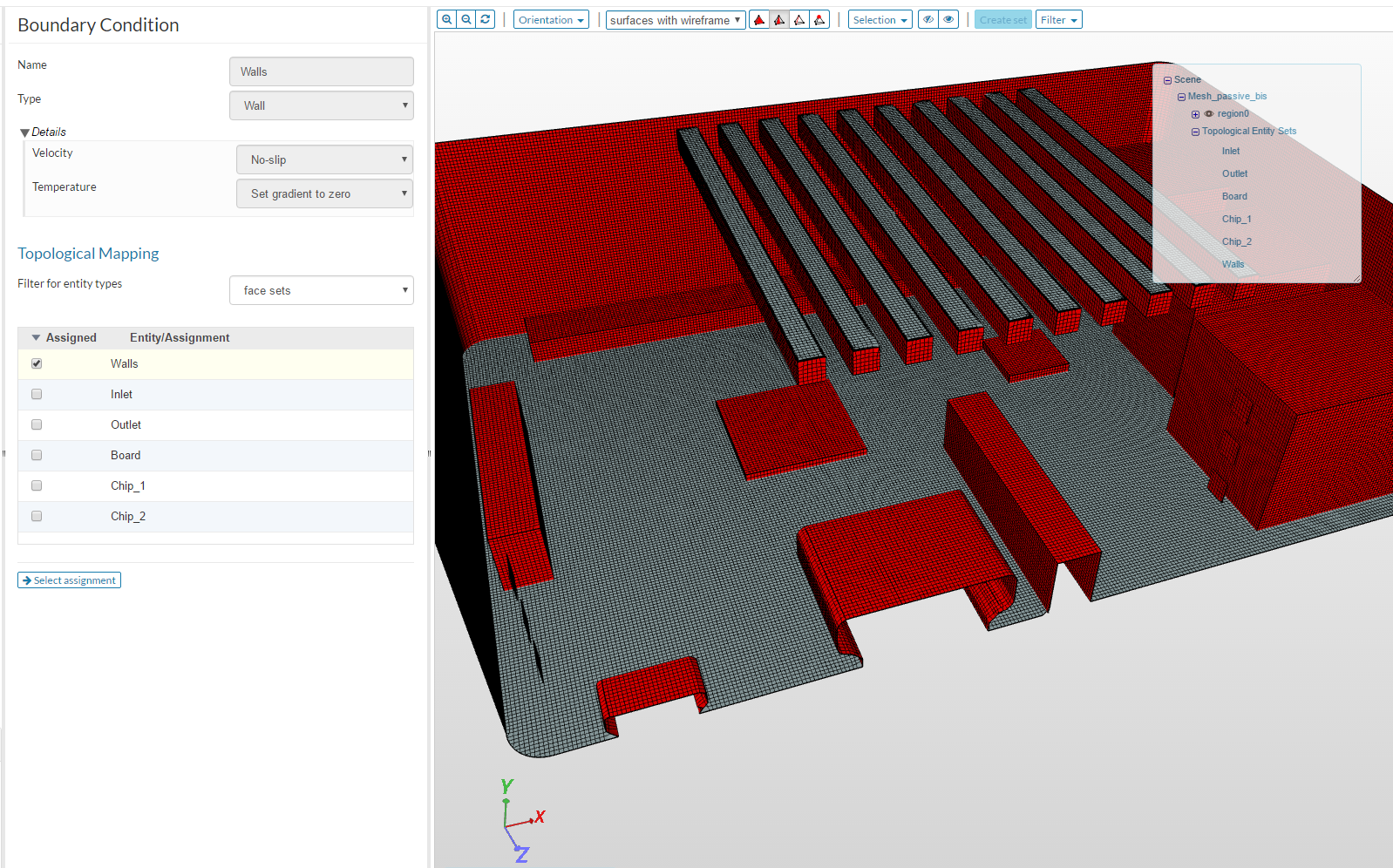
P.S: Make sure you set up your boundaries in a proper manner!!!
Hi @jousefm,
unforunately I have the same problem.
I meshed again the component (passive) and set up the boundaries again for a new simulation, I think in proper manner, but the simulation is slow and didn’t arrive to the convergence ( the time exceeds), but the convergence plot is smooth!!
checked your profile and noticed that your boundary conditions in the section “Walls” are wrong! Check them again and make sure you do not assign two boundary conditions for the same entity. Try it again and let me know how it worked
The 2nd simulation of mine also converged before the 2000th step. I had to lower the U and p residuals requested to reach t=2000. But since in this way the simulation at that final time is still not converged with the renewed and more strict residuals, I had also to change the write interval step not to risk to have no results written at t=2000.
hi @jousefm,
I think I was careful, but my first simulation is sleeping… and in your simulation the board plate is in WALLS BC!!!
WALLS is= all faces element - board - chip1 - chip2 - inlet - outlet, right or not??
neither inlet, outlet nor the chips1/2 are walls in my boundary “Walls”. With my settings I get the same results as Milad (at least in my passive cooling, did not adapt my settings in my active cooling - so treat with caution! ;))