No, it doesn’t have to if you don’t include the wing mounts to the chassis.
I don’t think having face intersection is a problem. As long as the geometry is watertight and all faces point outward, it is meshable.
No, it doesn’t have to if you don’t include the wing mounts to the chassis.
I don’t think having face intersection is a problem. As long as the geometry is watertight and all faces point outward, it is meshable.
Hello,
How do I set the CAD in the mesh creator to have the lower point at Z=0? Because when creating the mesh box I have to insert Min.Point (z)=-0.592 instead of Min,Point (z)=0 in order to have the wheels touching the ground.
If I can’t move it, do I have to apply the height correction also when defying the rotation of the wheels in the simulation designer?
Thank you in advance.
Hi all,
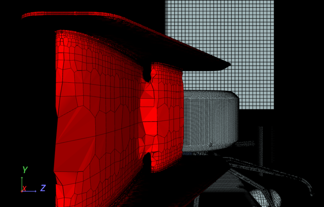
While creating the mesh, I am just facing the same problem as the one @CarlosPrieto mentioned before: the gaps between the flaps of our FW are strangely filled with cells. Besides, the cell density drops dramatically over the surface of the flaps, at least in comparison to all the other parts of the car (and the refinement has been defined as it is in HW2 description).
However, the solution @pfernandez gave to this problem is not applicable to my case, since I have only a single part for all the FW. So my questions are:
Thank you very much, any help goes down well.
[Project link]
[Screenshot of the finished mesh]
Hey,
Got a similar problem and simulations ends possible due to numerical instability.
What you can do is export just the FW as stp to simscale and simulate it alone, however you wont be able to merge with the rest of the car as we dont have the car in stp.
PS:
Full project(in stl): https://www.simscale.com/workbench?publiclink=4c025800-7f09-4314-ae0f-e39671b4abc0
Only FW(in stp): https://www.simscale.com/workbench?publiclink=74a94ba6-bfaf-471a-81c9-42a0378331d4
Also if I convert the stp to stl the mesh gets better, but still get the same error during simulation.
Conversion test: https://www.simscale.com/workbench?publiclink=649bf6d1-ede4-44bf-a3ef-c6cfaa2d8398
Best Wishes,
Luis Calzado
Ok, thank you very much, it was helpful. For the moment, I will try to carry out the simulation (I hope it will be enough the the Homework 4, since many people are facing this kind of problems). And then I think I will try to find out what is exactly happening there, since it is really weird.
I think the problem is in the cad, this happened to me the last time, when you have overlapped surfaces, (surfaces on top of each other) this can happen, so what i will suggest is to let the surfaces intersect with some mm instead of trip them.
I think the problem is in the CAD this happened to me the last time when you have overlapped surfaces, (surfaces on top of each other) this can happen so what i will suggest is to let the surfaces intersect with some mm instead of trip them.
Hi,
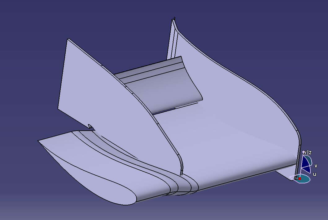
I tried multiple times ROTATING the orientation in every rotation in CATIA but never got the result I wanted. It’s frustrating and sad since so many hours have been spent.
Every time I rotate in any direction I would get the wing facing the opposite direction and not in the right position.
Sincerely,
Mislav Bosnjak
Do you mean in the area where the FW ‘touches’ the nose? If so, what I have done there is in fact let those surfaces intersect…
Thank you for your help
@D_Izquierdo for all the parts, avoid overlapping
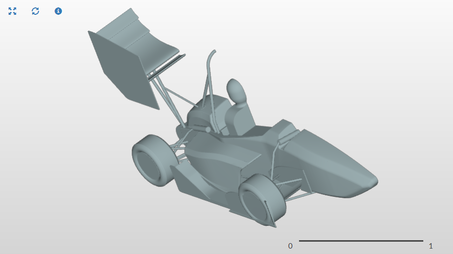
@ mislavbosnjak it’s clear from the picture that you are designing your front wing the the opposite direction of the STL model, you have to rotate the model in CATIA 180°,
Hi @svianello yes that’s right pleasedownload the new version of the STL model, we have fixed the position, Z=0 to the ground.
hi @mislavbosnjak send me your STL at amouffouk@simscale.com and i will see
Greetings Akrem, @anon96223049
Thanks You for the message!
I will send you my current project, and in the meantime I will design the sam front wing in an opposite direction in Catia. If there will be any positive results I will message You as soon as possible.
Sincerely,
Mislav Bosnjak
Project link: https://www.simscale.com/workbench?publiclink=b8e80a44-f8c9-42c8-8ed4-7b63857a5deb
For the .STL (only FW) the mesh looks pretty good, doesn’t it? And the same I would say for the .STEP… (By the way, do you know why in the .STL case 9 M volumes are created -only 2 M for the .STEP-?).
However the same errors appear again and again… But the simulation for the .STEP worked fine!! Do you know why did it work? It would be a valuable information.
And how did you split the .STEP FW in several parts? I am not able to do it.
@mislavbosnjakI can’t open your project, please share a new link, and you don’t have to design a new FW all what you need is to rotate it around Z with 180°.
Hi all, sorry for the lateness however when merging my wing file and car model together and uploading it onto a new project it appears to keep coming uop with only the wing. Please help i am really into this course and need this outcome for my university FYP. my link is https://www.simscale.com/workbench?publiclink=c33e9cb2-0fbb-4954-80f4-455740104684.
The scale of the wing and cartesian box was differente as I was making a couople of tests, but dont think that would impact the result. To be honest i dont know why it worked as step, same procedure was used. Several parts you mean faces? By default it exported the way it is (I’m using Siemens NX10). What I know is that there is an option on what would be exported and I marked solid and surfaces.
Hey,
Your problem probably is the scale, your wing is much bigger then the rest of the car, you can see on the bar on the right under solid_0 that the car parts were also imported to simscale.
Try to rescale your wing (0.001 for example) and you should be fine
Hi @jkendrick please follow the same steps in the tutorial to merge your front wing with the car model, in your project looks like you are uploading only the front wing.