Recording

Homework Submission
Submitting all three homework assignments will qualify you for a Certificate of Completion.
Homework 3 - Deadline: Date, 05th of June, 11:59 pm
Exercise
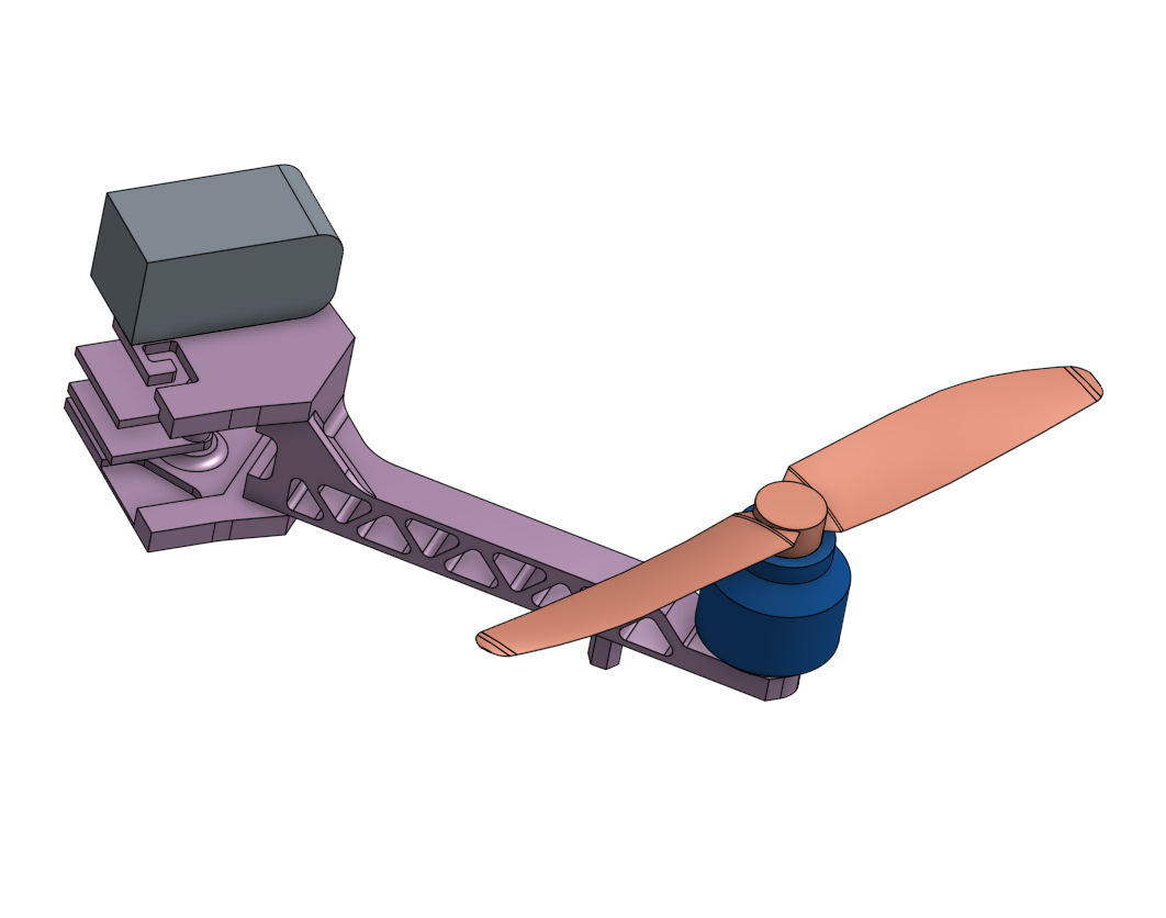
In this level of the homework we will set up a more realistic simulation of the drop test. We will therefore reduce the simplification of the model by using more components with different material properties.
We will investigate the effect of changing the masses of the battery and the motor on the maximum stresses. Therefor run four simulation runs with 10% increased masses of battery and motor in each simulation (add 10% of the initially given mass in each run). To change the mass just change the density of the materials assigned to motor and battery. Additionally we will investigate the effect of drone arm truss thickness on the overall drop dynamics
Step-by-Step Instructions
For this project you will be given a link to the OnShape CAD project. Onshape is an online CAD modeling platform, which allows full CAD modeling from the web browser. Onshape models can directly be imported to SimScale. Please make sure you have an Onshape account (Community account is free).
If you have the Onshape account you can make the changes to the model and then import it to the SimScale.
Geometry
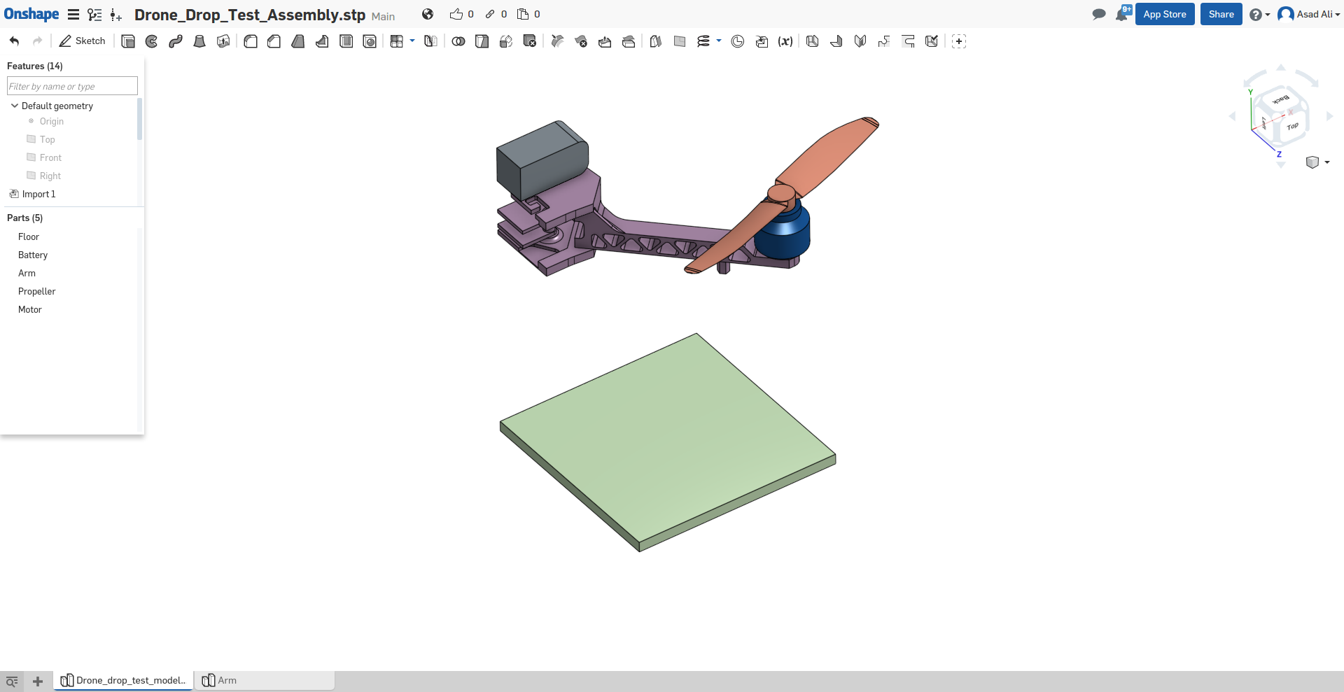
To get the Onshape model click on this link. You will be directed to the Onshape CAD project. Make a copy of the project by click the Make a Copy button.
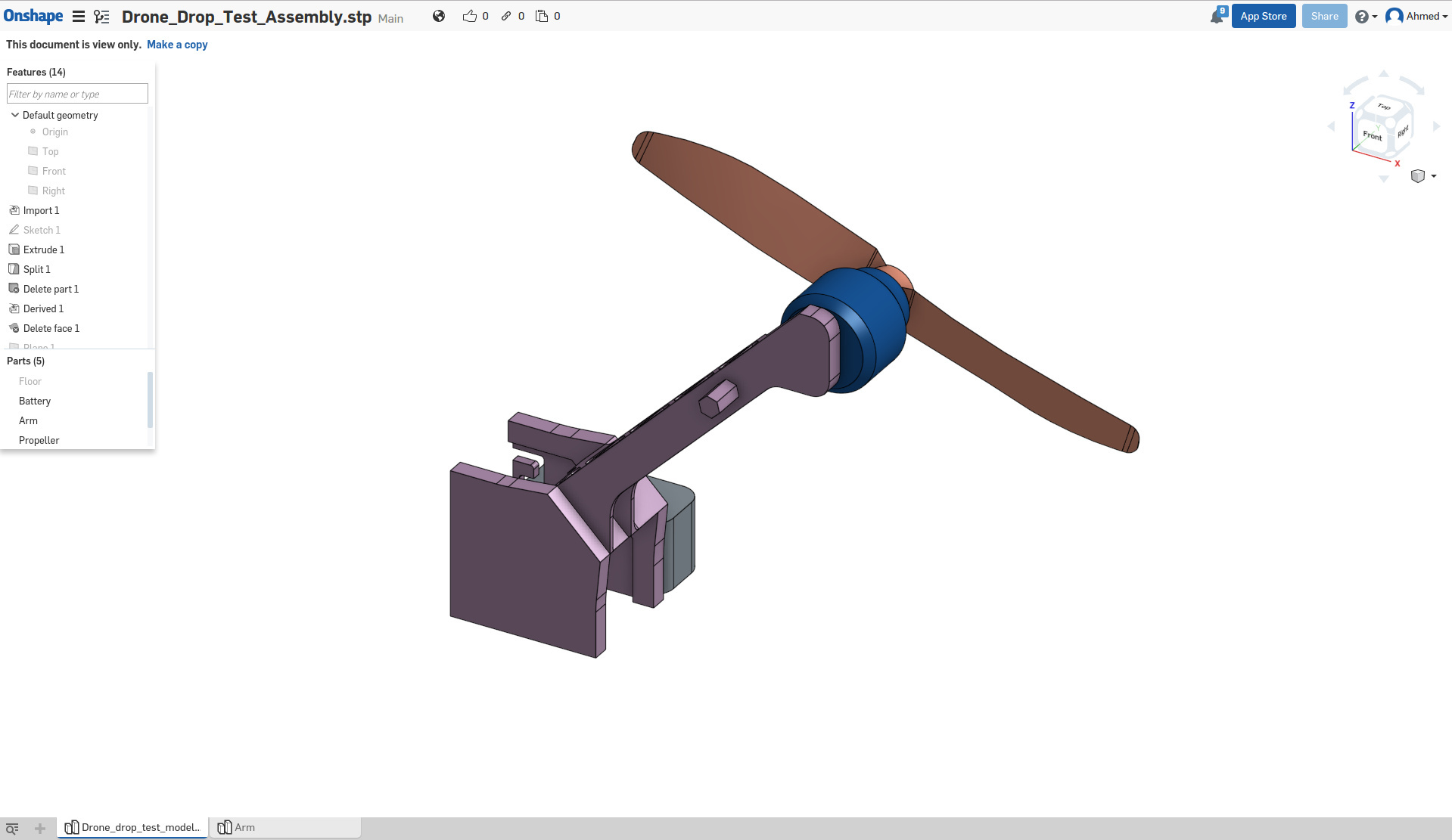
Once the project is added to your Onshape workspace you will be able to modify it.
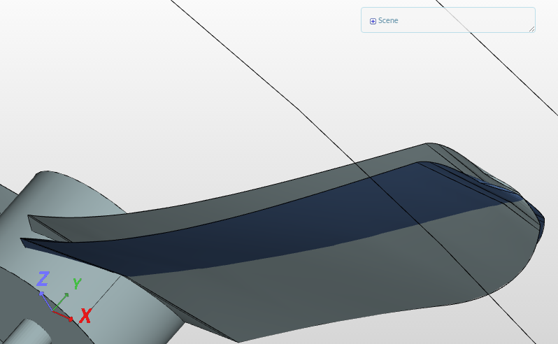
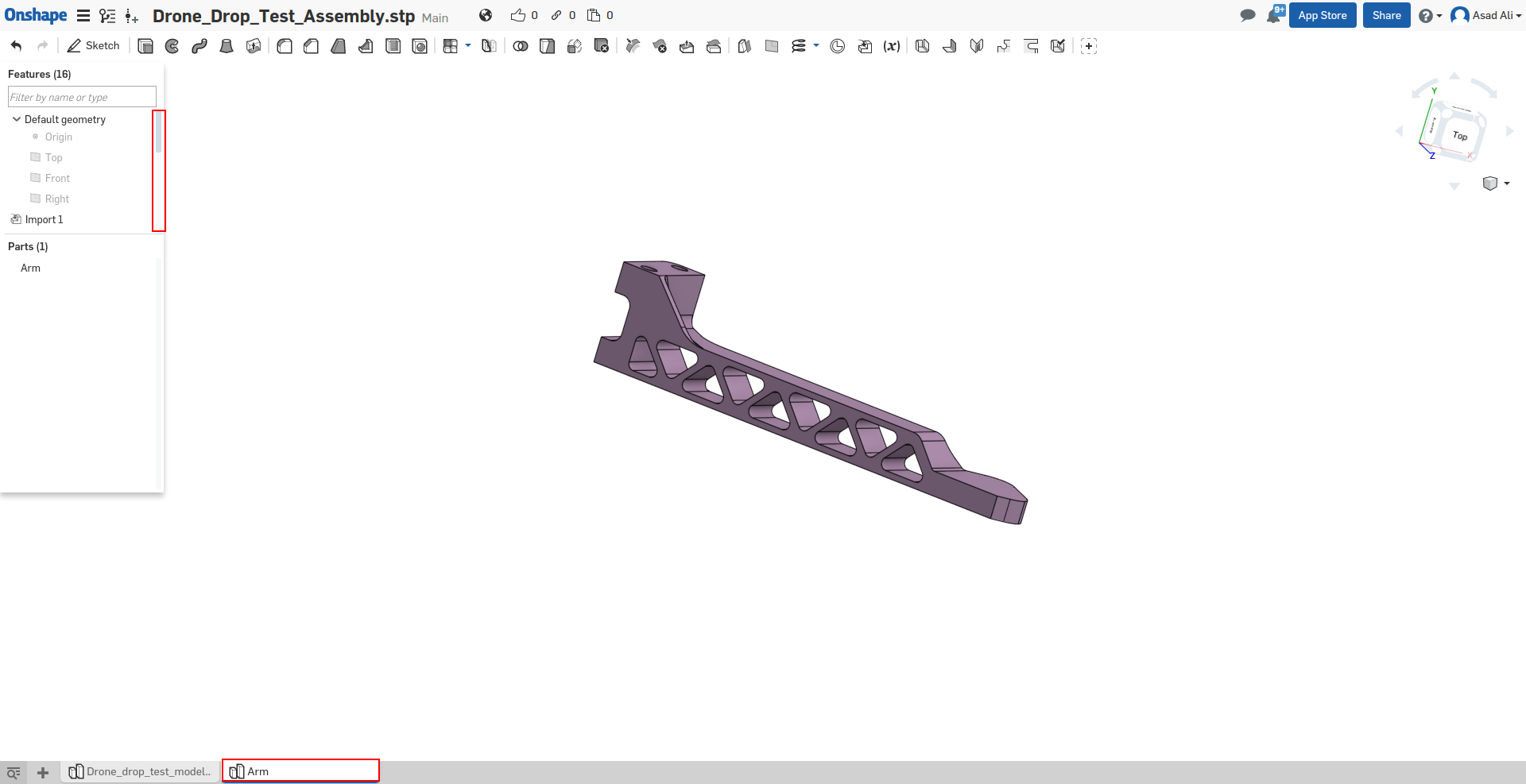
To change the thickness of the arm truss, move to the Arm tab in your CAD project. In the left column you will find the CAD operations tree.
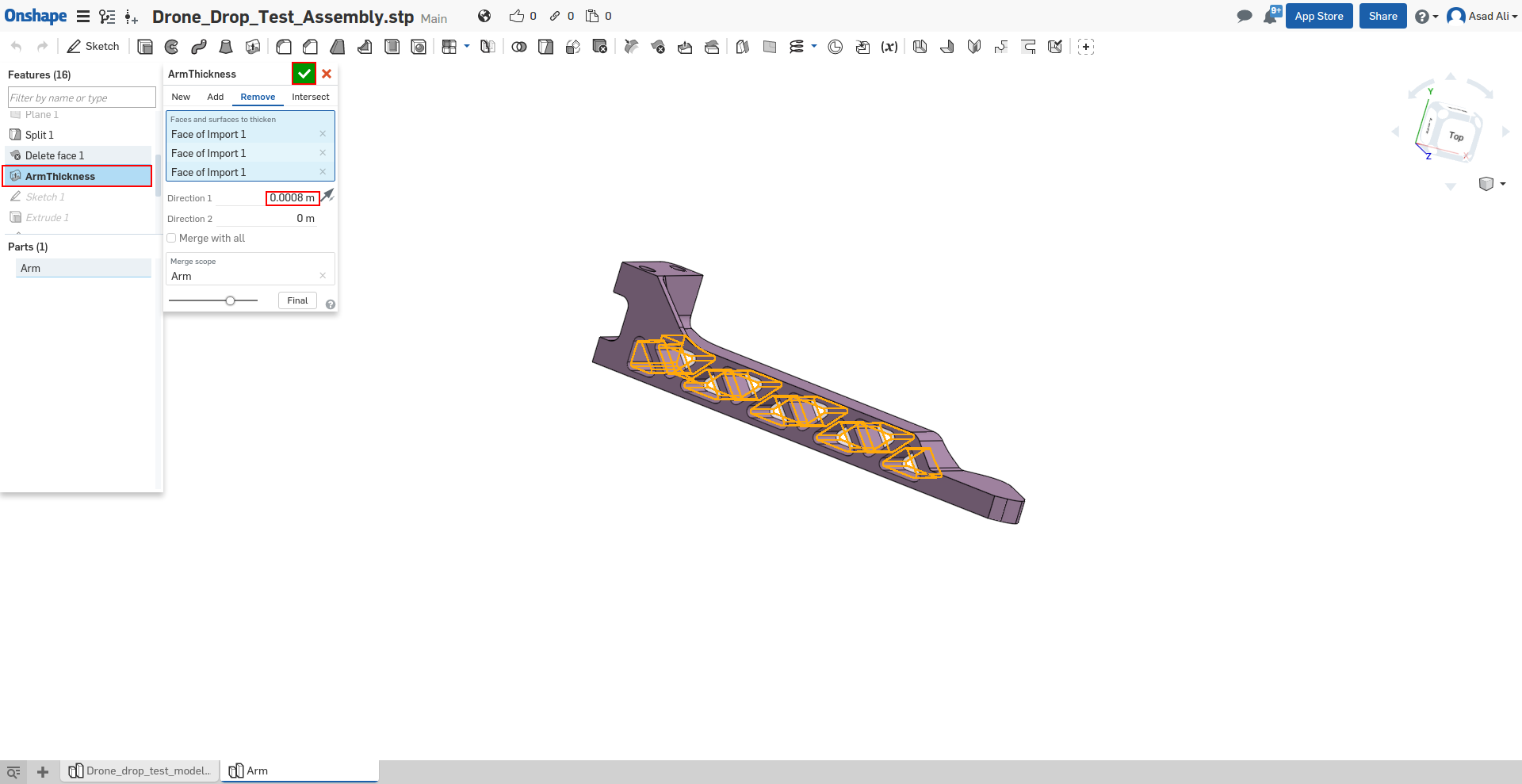
In the operation tree find the ArmThickness and change its value (between 0 to 0.0008m). Save the selection by pressing the relevant button.
- Note: this is a relative thickness, the idea here is to investigate the effect of the truss thickness on the overall design.
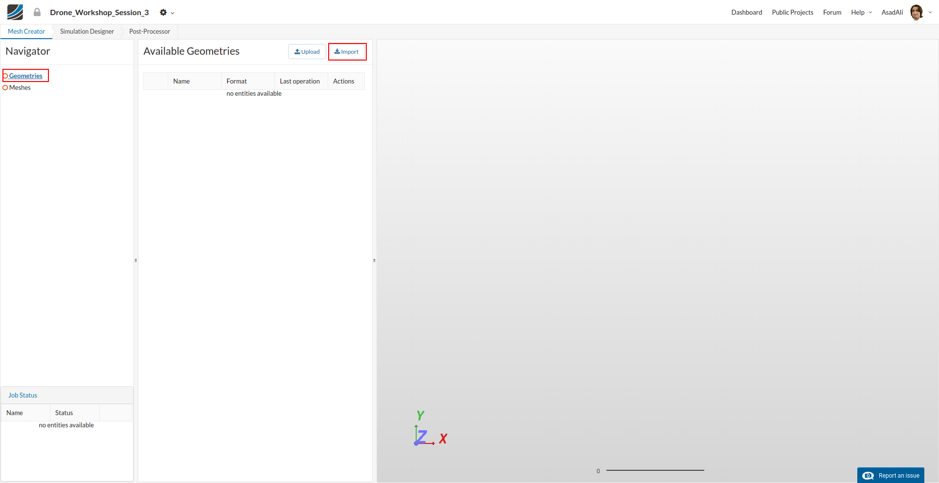
Once you are done with the geometry modification, import the geometry into SimScale project. Make a new SimScale project and click Import under the geometry. Make sure you are logged in into your Onshape account.
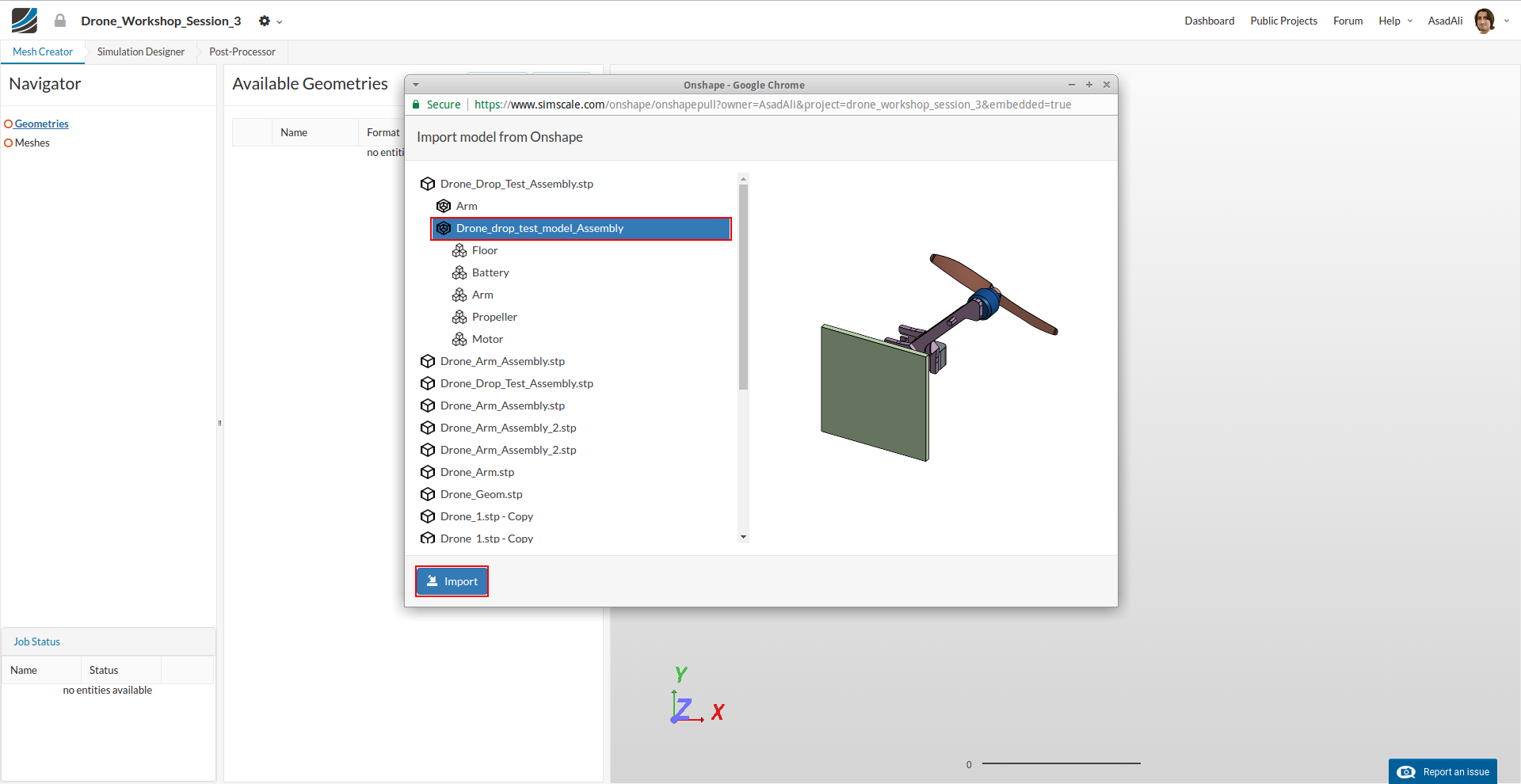
A new window will open where you can select you Onshape CAD project. Select your required model and and press Import to import the geometry into SimScale.
Meshing
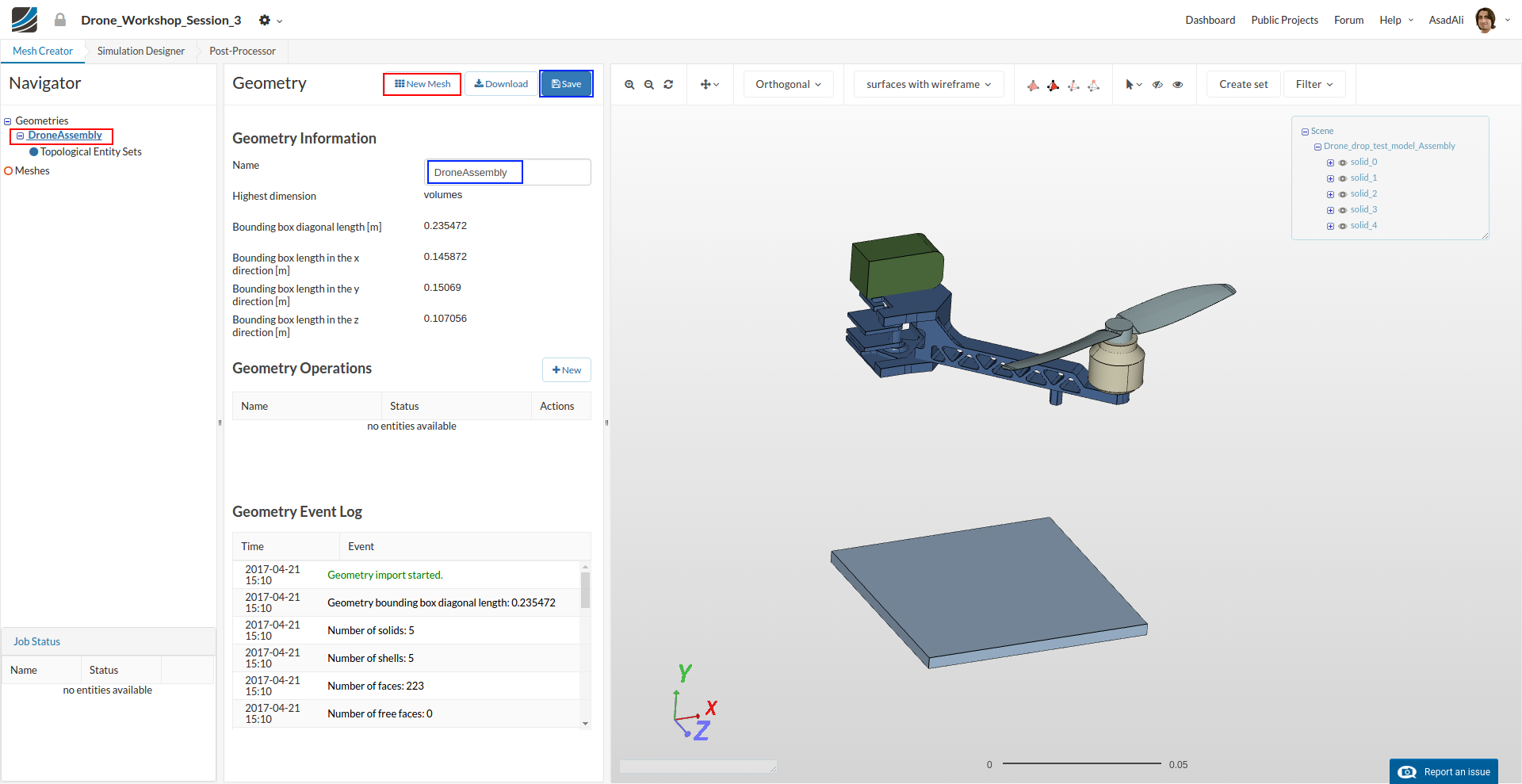
Once geometry is imported to your workspace you can rename it. Click on the New Mesh to make the mesh using this geometry.
A new middle column with the mesh parameters will be added where you can set the mesh parameters.
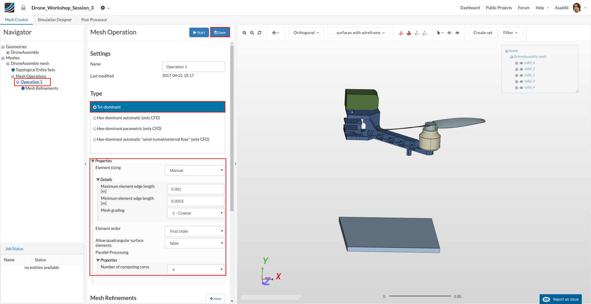
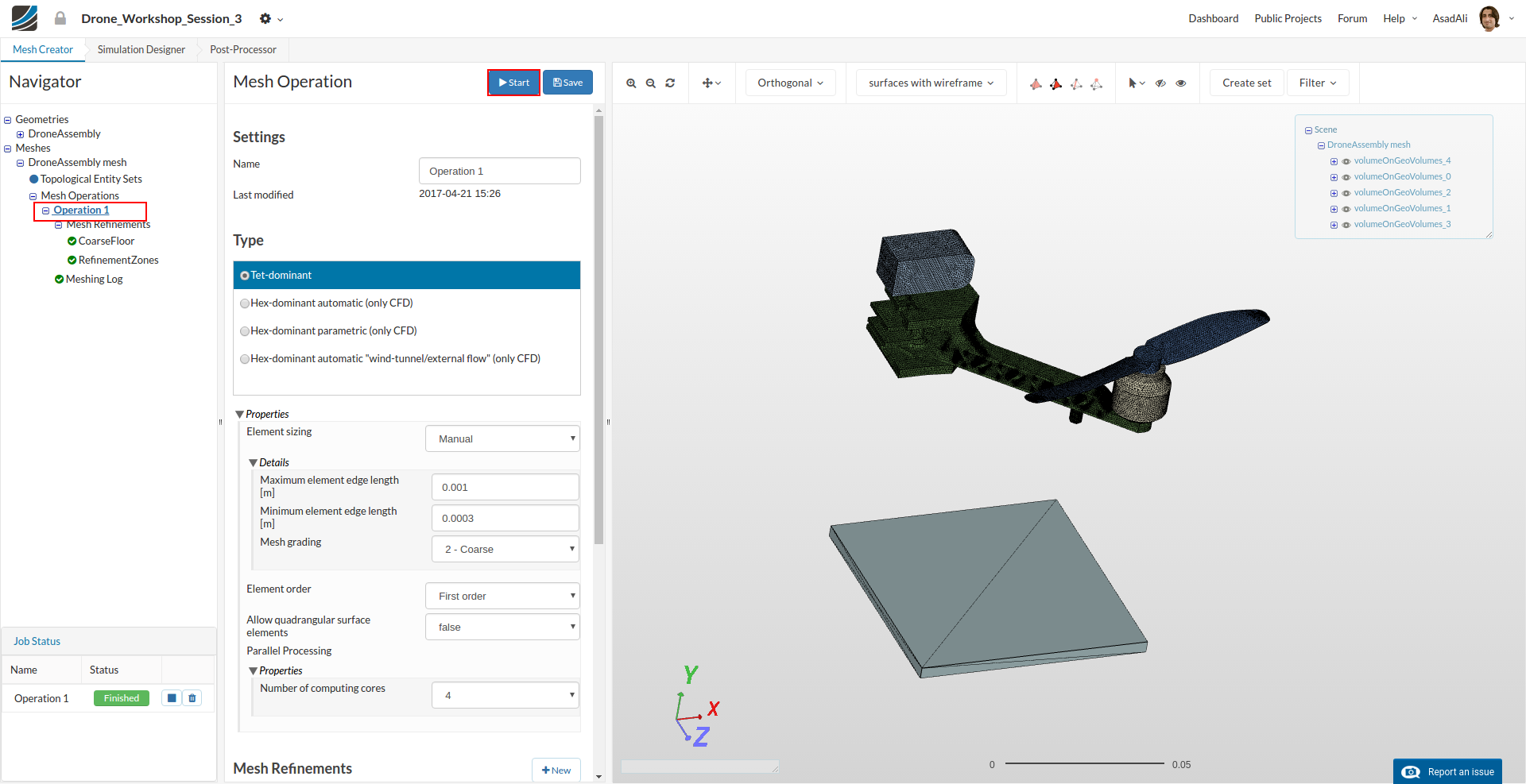
Select Tet-dominant from the list and define following parameters:
- Element Sizing: Manual
- Maximum mesh edge length: 0.001
- Minimal mesh edge length: 0.0003
- NETGEN3D fineness parameter: 2 - Coarse
- Number of processors: 4
We now have defined a range for the base mesh size which is fine for regions where we are not expecting high stress. Here you should keep in mind that, in general, the mesh size is related to the local accuracy of the simulation. It is therefore necessary to refine the mesh in those areas where high stresses are expected.
We will now apply local refinements on two areas where we expect high stresses and high deformations and an additional local refinement to the floor to decrease the mesh resolution.
Click on the Mesh Refinements item which was added to the project tree. This will open again a menu in the middle column. Press New to add a new refinement.
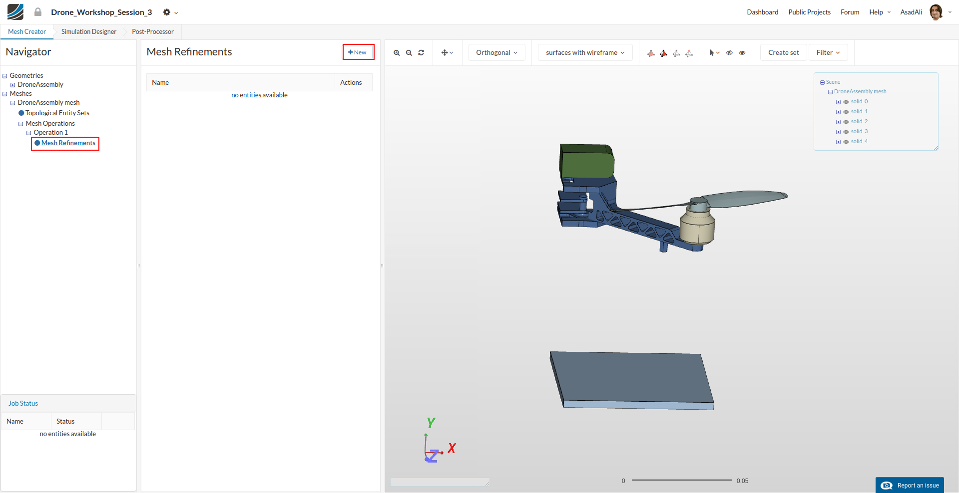
Now you can specify the mesh refinement.
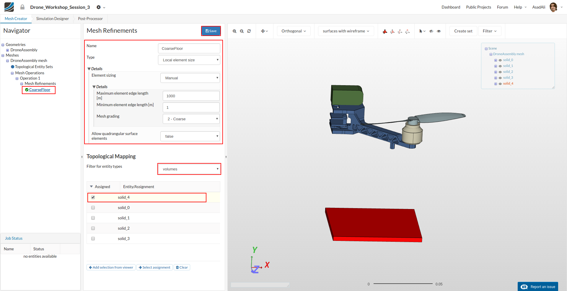
- Name: CoarseFloor
- Maximum mesh edge length: 1000
- Minimal mesh edge length: 1
- Mesh grading: 2 - Coarse
Select the floor volume and assign it for this refinement. Save the selection.
Create an additional mesh refinement by clicking on the New button which you will find again in the middle column when you click on the Mesh Refinements item in the project tree.
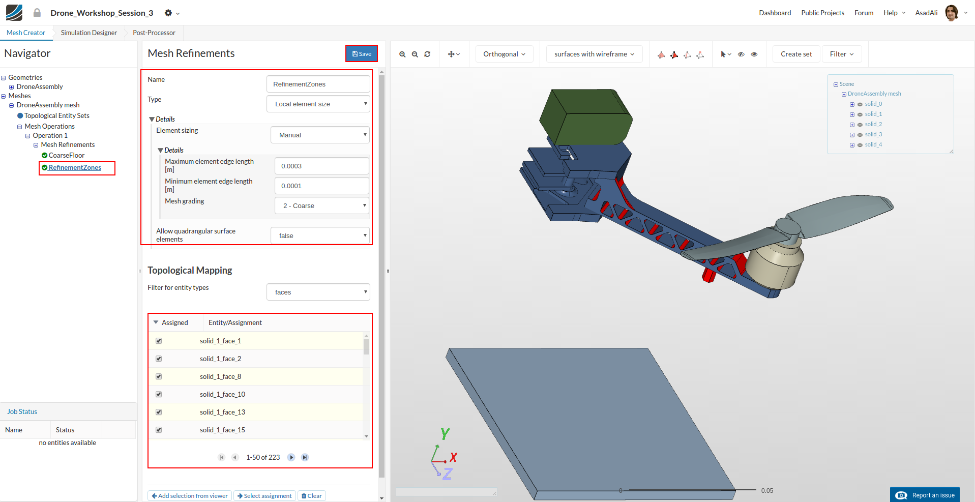
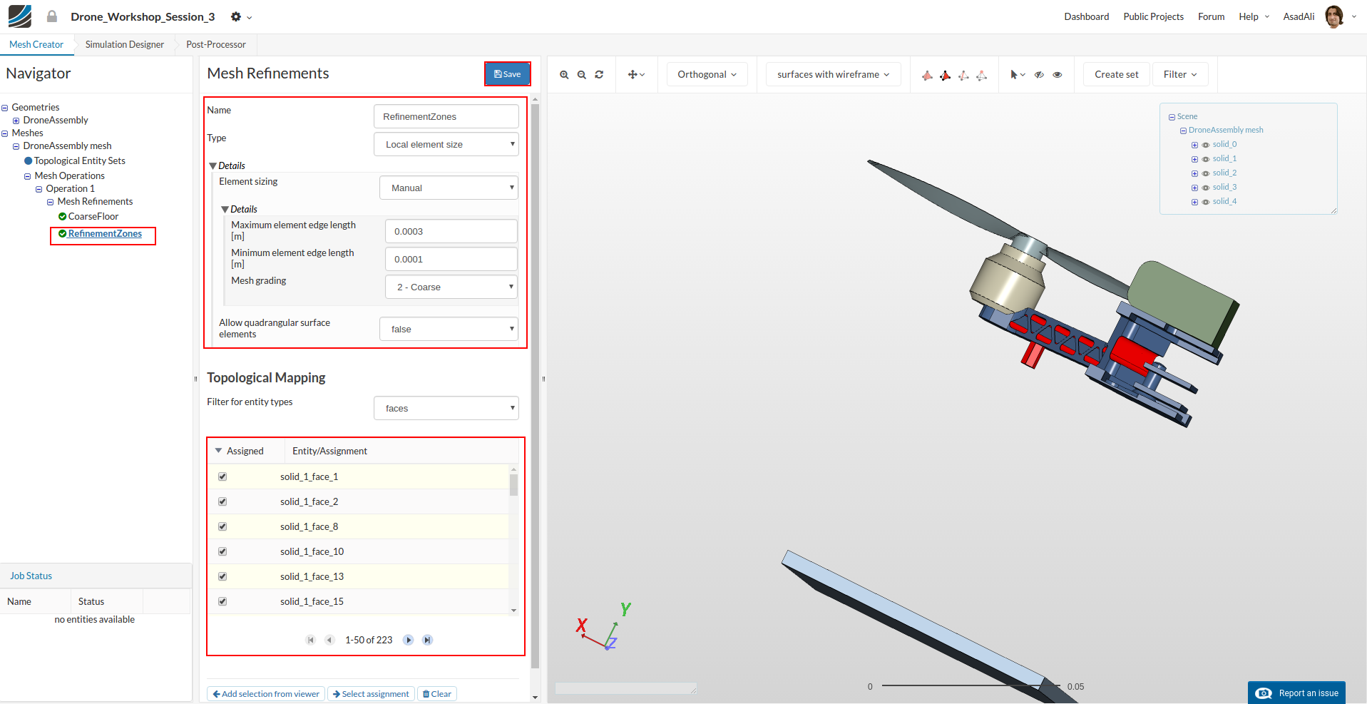
Now we will add refinement to some surfaces of the arms and the base plates. Specify the refinement as follows:
- Name: RefinementZones
- Maximum mesh edge length: 0.0003
- Minimal mesh edge length: 0.0001
- Mesh grading: 2 - Coarse
Next, assign this refinement to the faces where high stress is expected.
Now our mesh is ready for computation. Click on the meshing operation in the project tree and click the Start button.
Simulation Setup
After the mesh is completed we will set up the simulation. Click on the Simulation Designer button in the main ribbon bar.Click on the New button to create a simulation. Rename the simulation to “DropTestDesign1”.

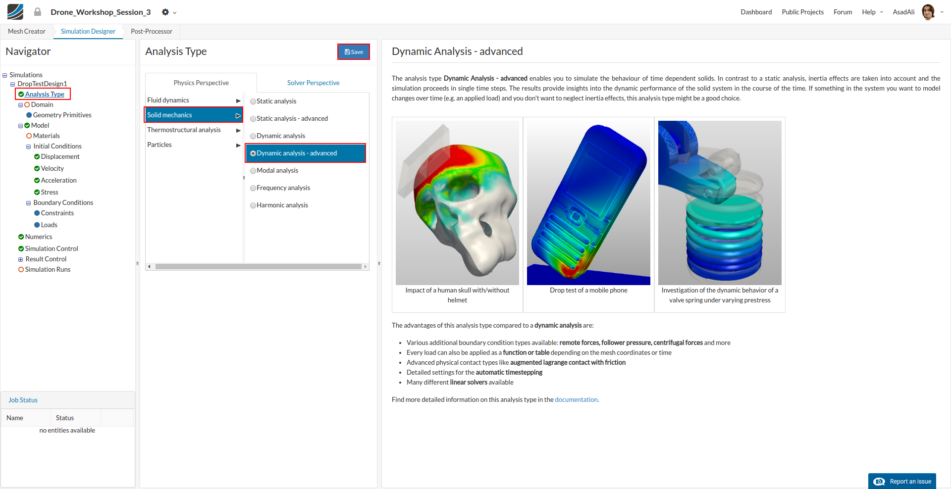
This will open an additional column in the middle. Here you can select what kind of simulation you want to run.
In our case we will run a Dynamic Analysis - advanced simulation.
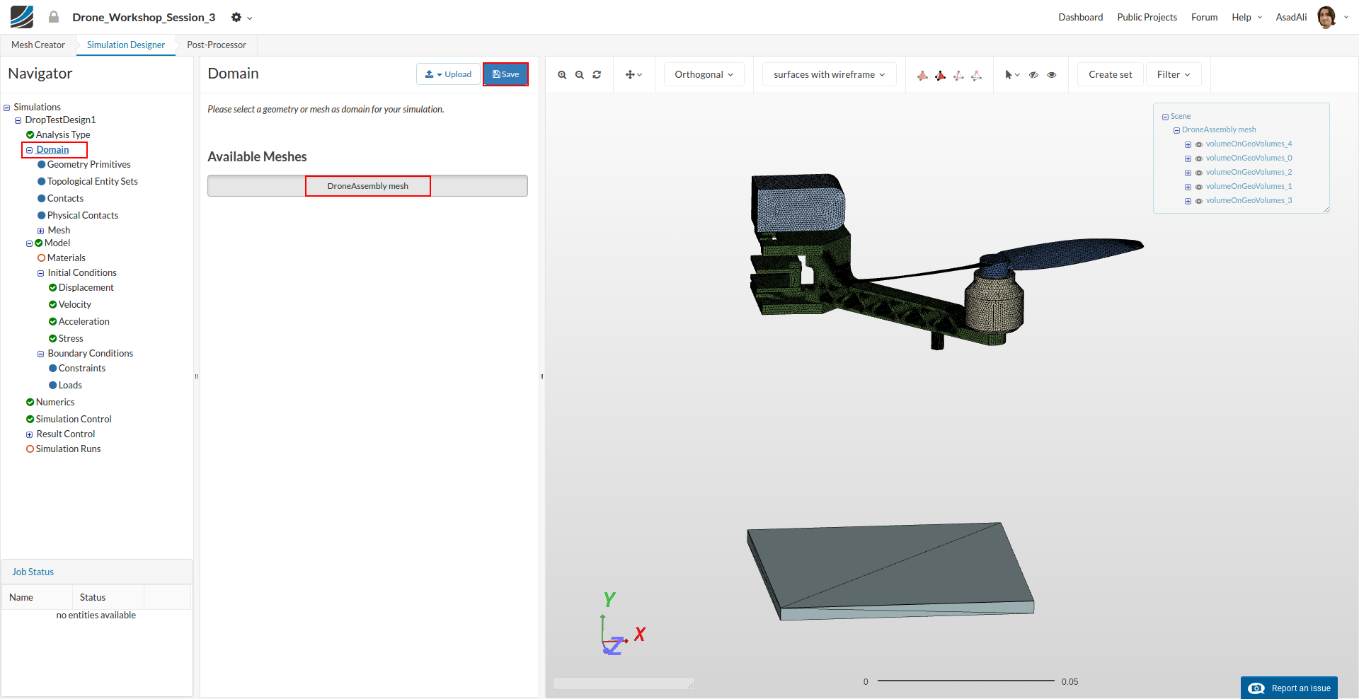
Next you have to specify which mesh you want to use for your simulation. Click on the Domain item in the project tree and select DroneAssembly mesh from the menu which disappears in the middle column. Don’t forget to save your selection.
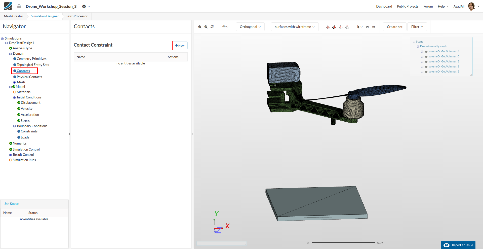
Since we are simulating an assembly of five parts, it is necessary to define Contacts which are describing the kinematic behavior of the parts.
Click on the Contacts item in the project tree which will open a new middle column menu where you can add new contacts by clicking on the related button.
Now we have to create four contacts which are connecting the parts. To select them graphically it may be necessary to hide some of the other parts.
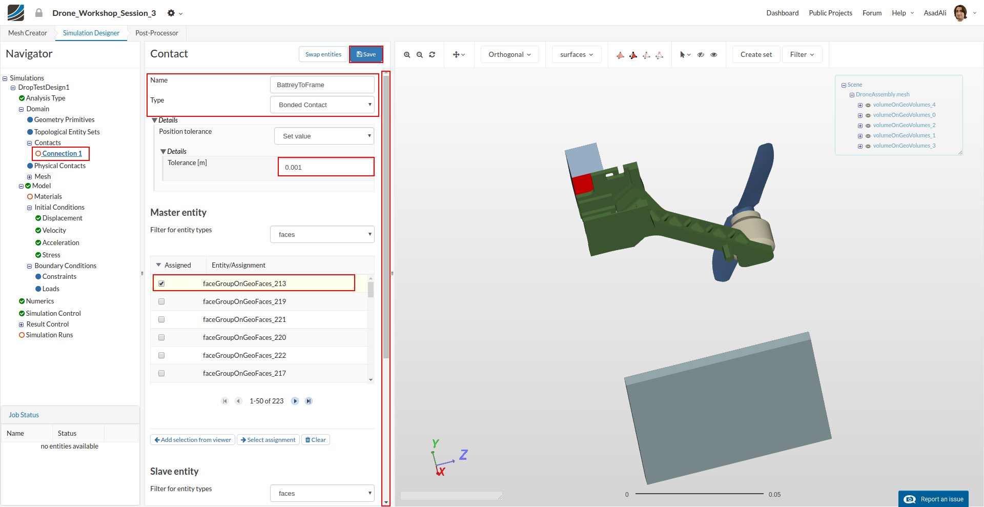
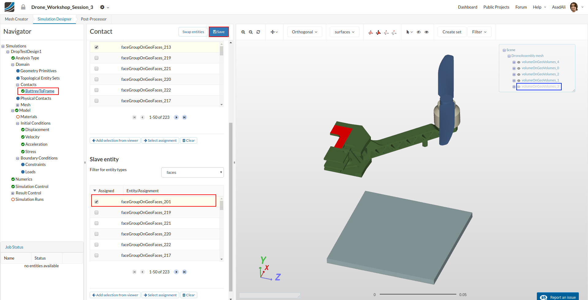
BatteryToFrame
This contact is necessary to connect the battery to the base plate. We will therefore define a contact between the contact area of the base plate (master) and the battery (slave).
- Name: BatteryToFrame
- Type: Bounded Contact
- Tolerance[m]: 0.001
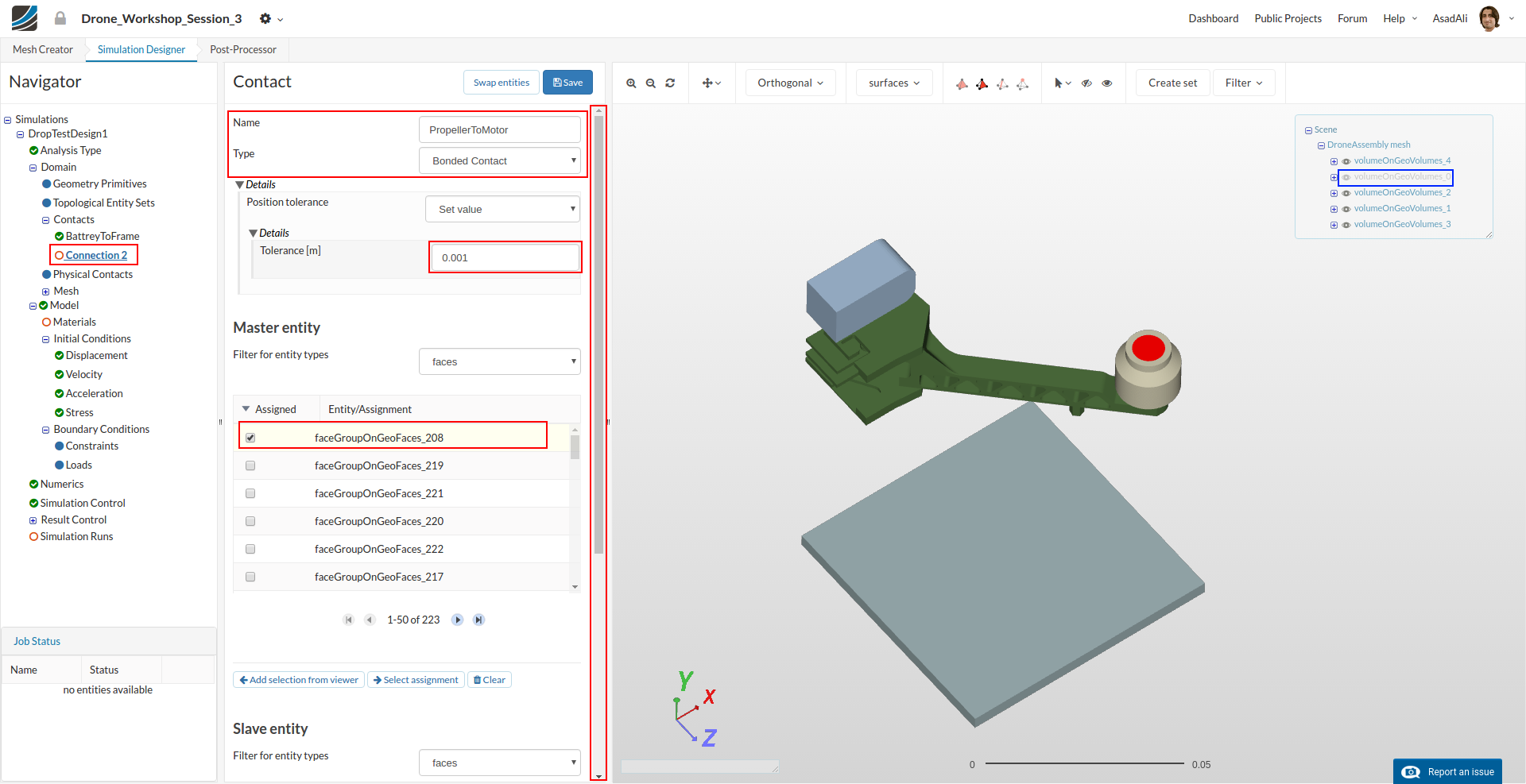
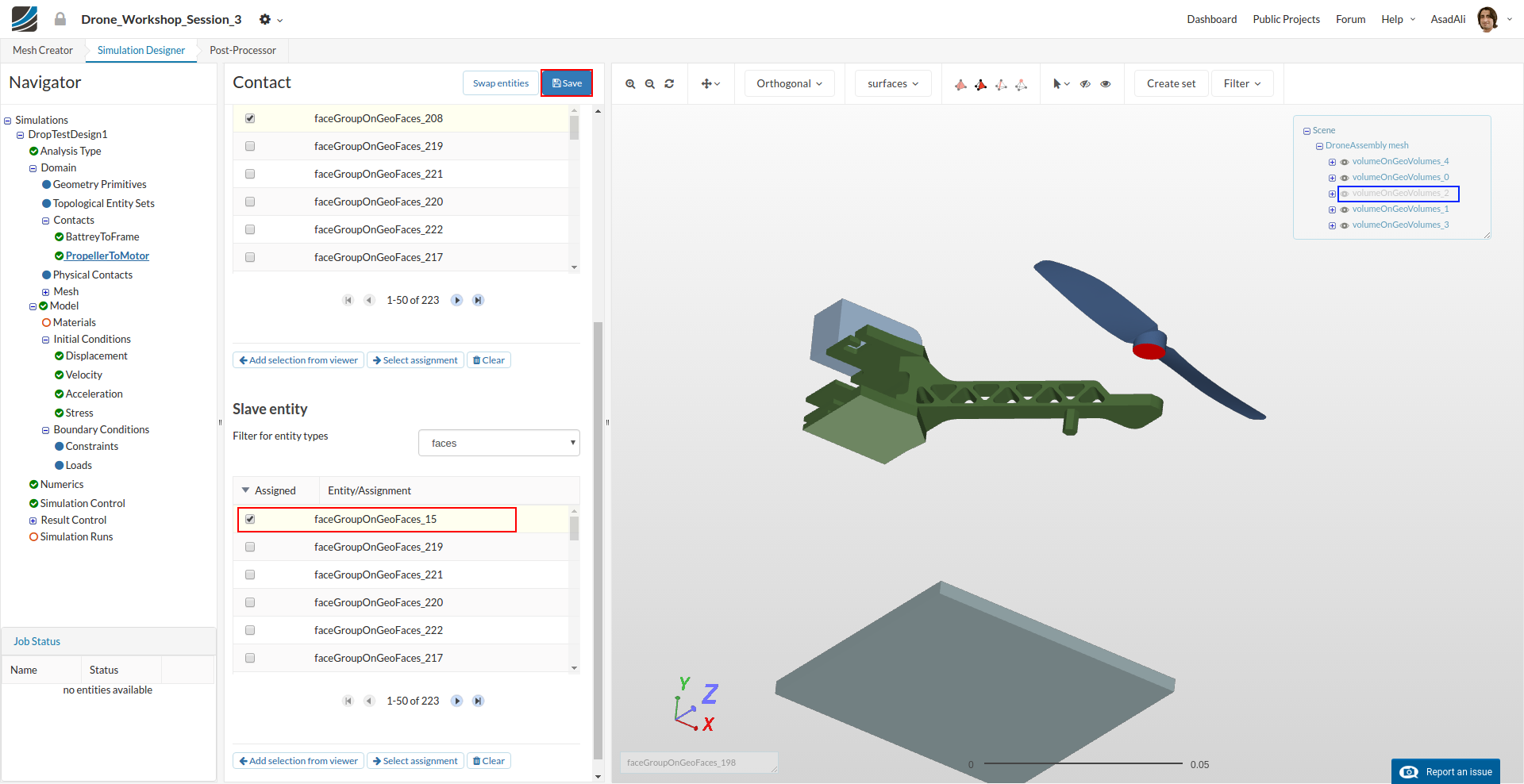
PropellerToMotor
This contact is necessary to fix the propeller on top of the motor. We will therefore define a contact between the lower face of the propeller base (slaqve) and the top face of the motor (master).
- Name: PropellerToMotor
- Type: Bounded Contact
- Tolerance[m]: 0.001
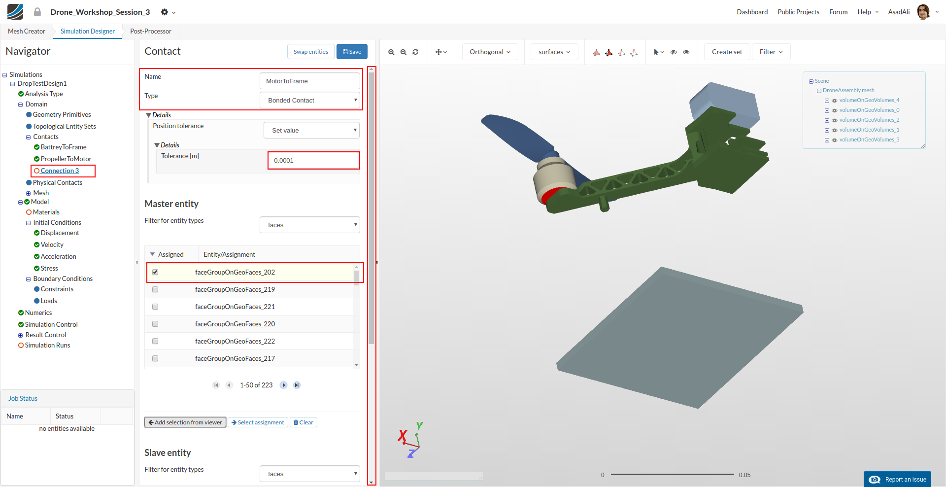
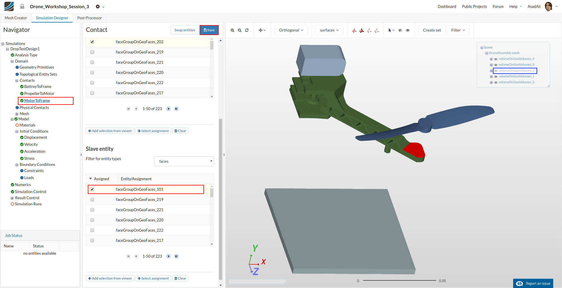
MotorToFrame
This contact is necessary to fix the motor on the arm of the drone. We will therefore define a contact between the lower face of the motor, the arm.
- Name: MotorToFrame
- Type: Bounded Contact
- Tolerance[m]: 0.0001
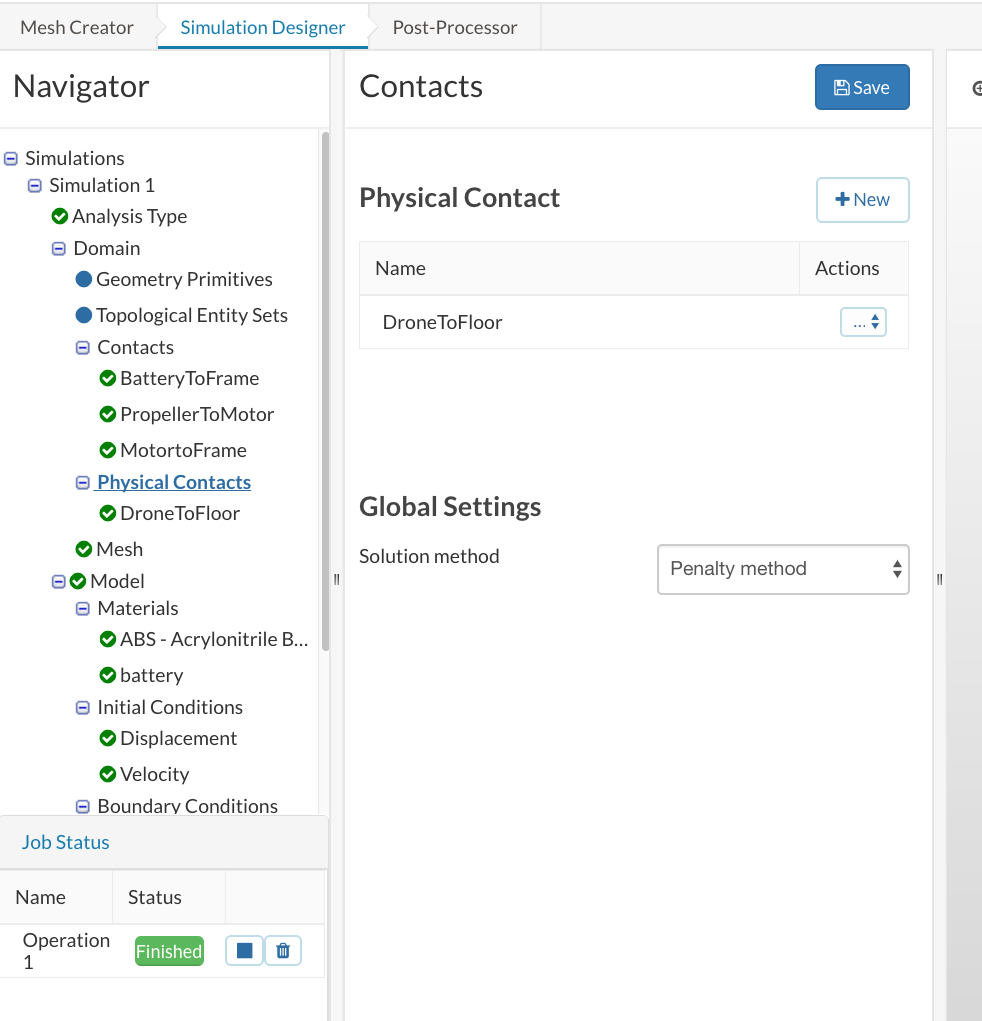
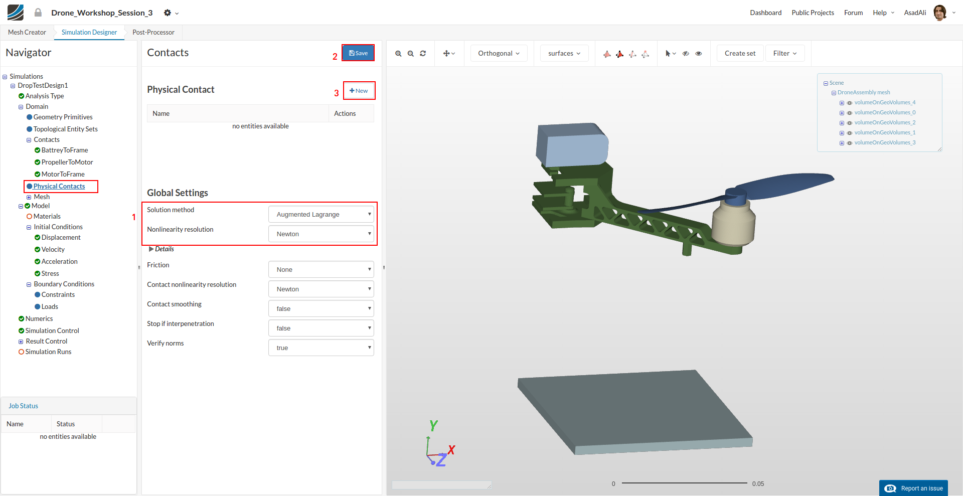
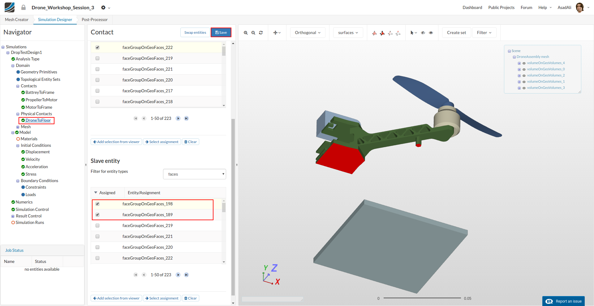
Since the drone will fall on the floor therefore we will define a physical contact between the drone and the floor. To make such a contact move to the Physical Contacts in the simulation tree and in the middle column set the Global Settings.
- Solution method: Augmented Lagrange
- Nonlinearity resolution: Newton
Next on the same page press New to define a new physical contact.
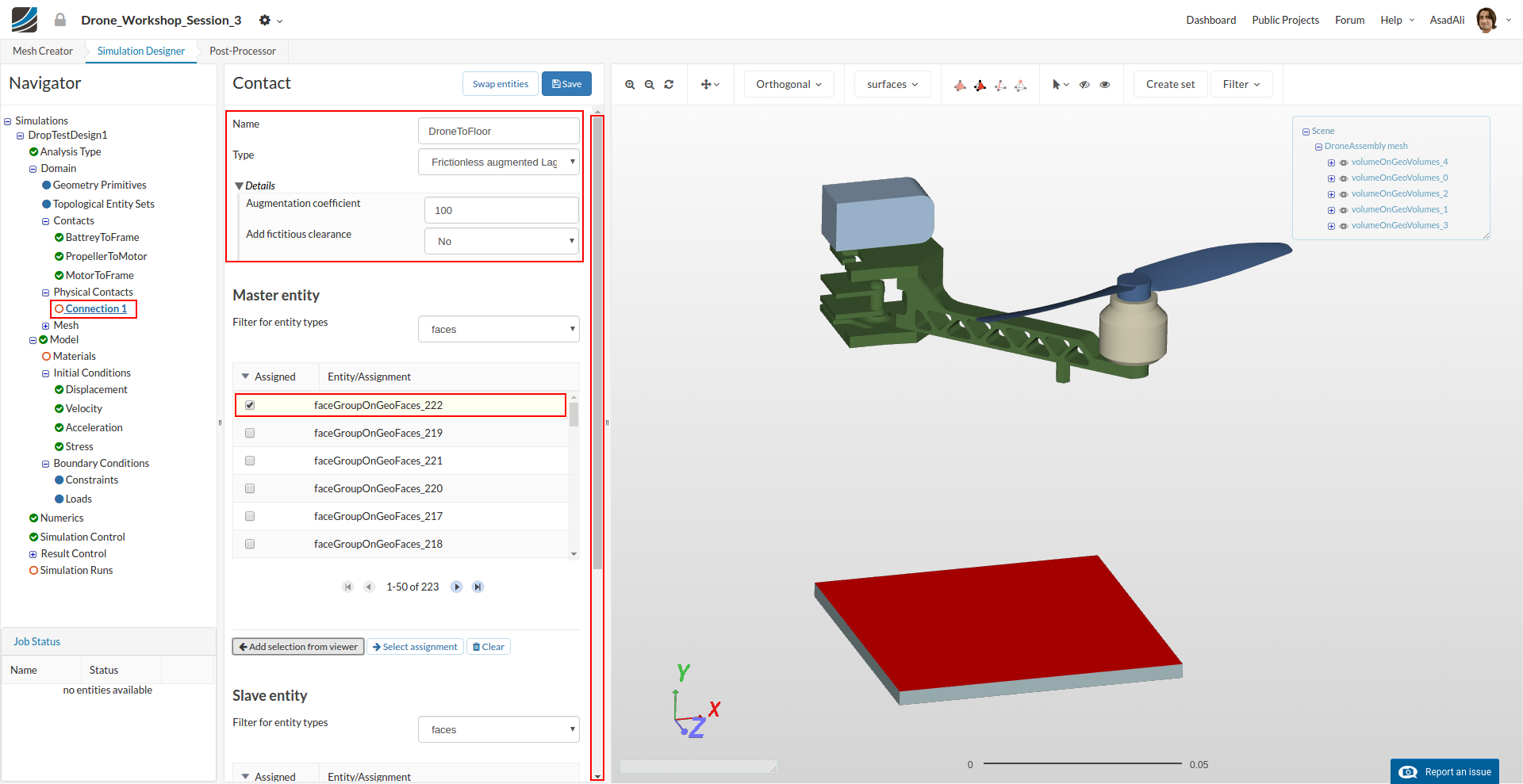
Set the contact parameters.
- Name: DronetoFloor
- Type: Frictionless augmented lagrange
Assign the master and slave entities.
Next we have to define the physical Model we want to use for this simulation. Click on the Model item in the project tree which will open a middle column windows. Here you can define the Geometric behavior as well as gravity.
- Geometric behavior: nonlinear
- g: 9.81
- ex: 0
- ey: -1
- ez: 0

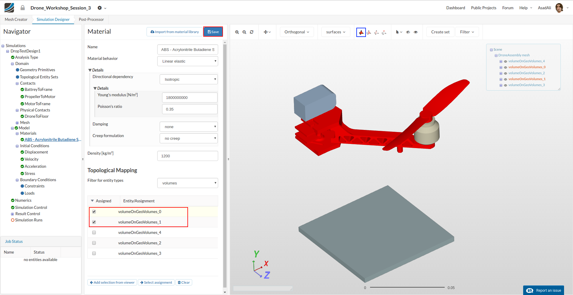
Now we define and assign material properties to the different parts. Click on the Material item in the project tree. This will open a middle column menu where you can edit and create materials and assign them to volumes. Click on the New button.
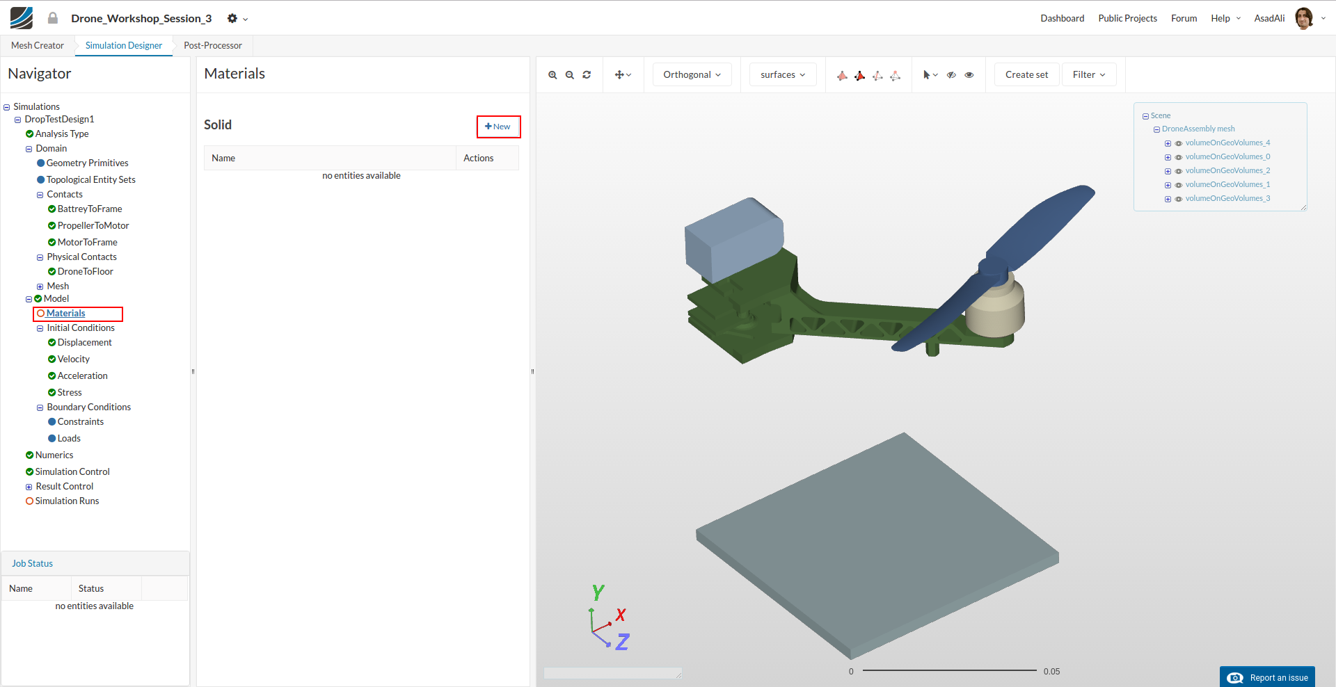
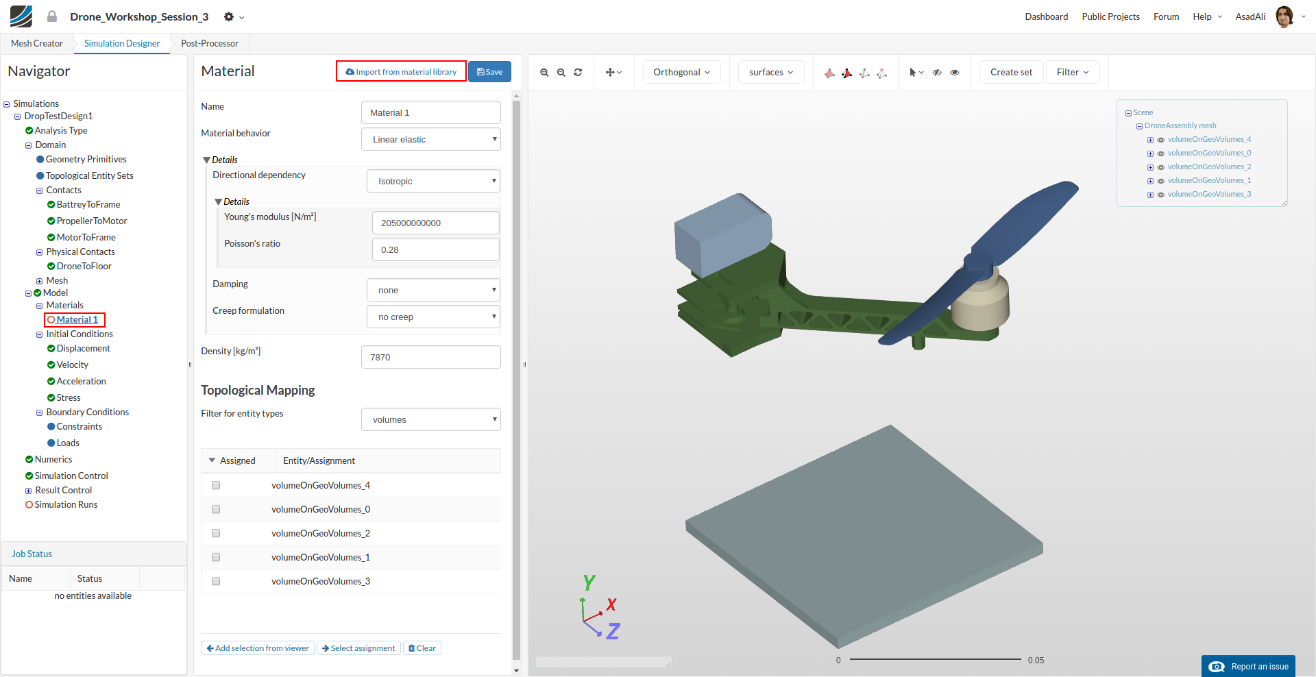
Now you can define your new material based on your own material proporties or access our Material Library which includes ready-to-use material models.
Click on the Import from material library.
Click ABS - Acrylonitrile Butadiene Styrene and press Save.
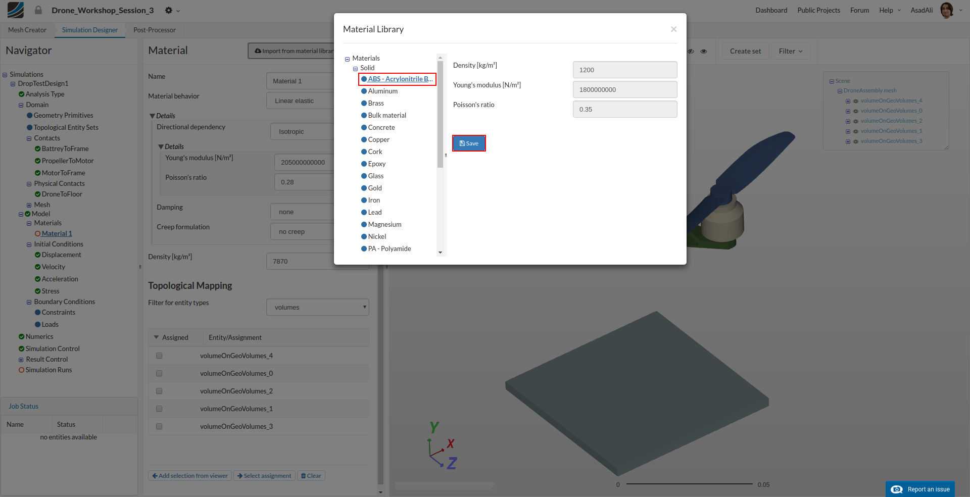
Assign this material to the arm assembly and to the propellers.
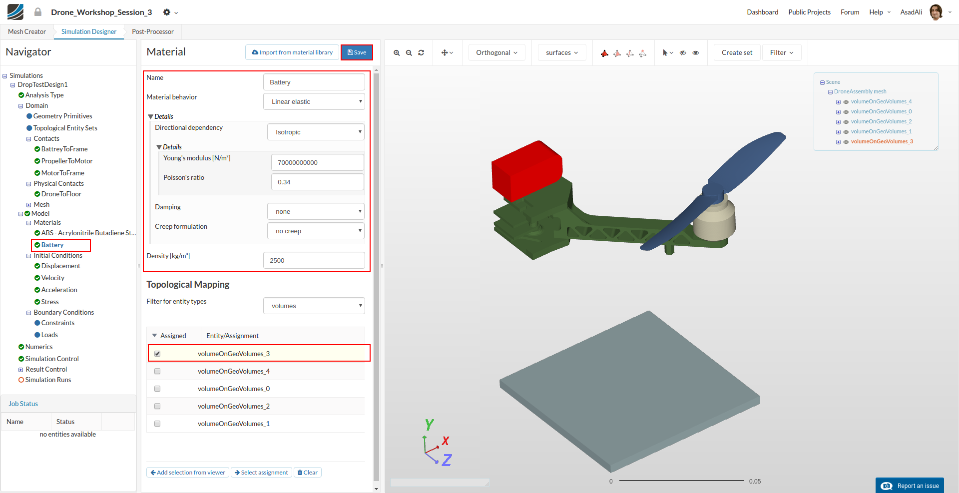
Battery
- Name: Battery
- Young’s Modul: 70000000000
- Poisson’s ratio: 0.34
- Densiy: 2500
Assign the material to the battery of the drone.
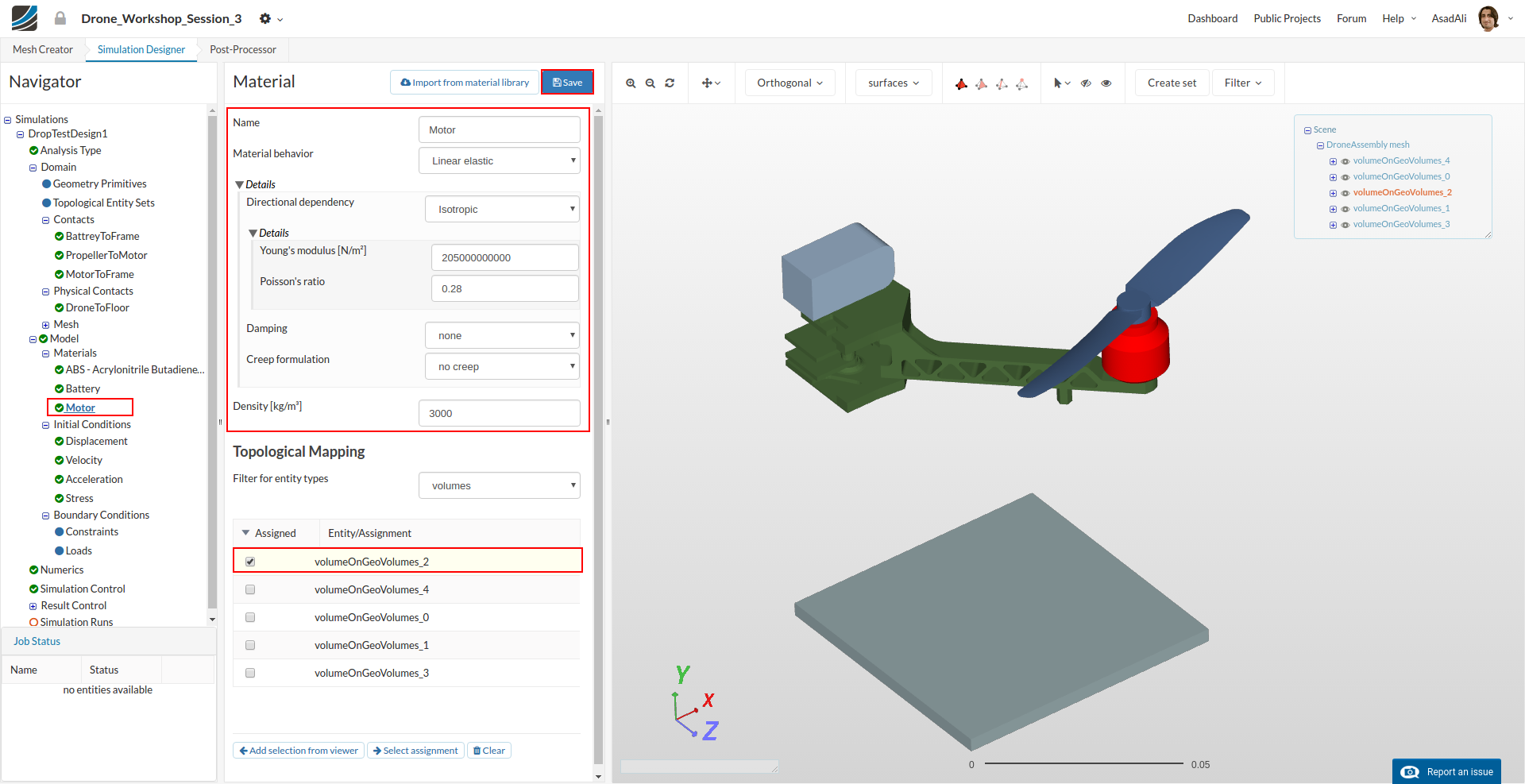
Add an additional material to your project tree.
Motor
- Name: Motor
- Young’s Modulus: 205000000000
- Poisson’s ratio: 0.28
- Density: 3000
Assign the material to the motor.
Floor
- Name: Floor
- Young’s Modulus: 205000000000
- Poisson’s ratio: 0.28
- Density: 7870
Assign the material to the Floor.

Since all kinematical and mechanical relations were defined, we will now take care for the interaction of our model with its environment.
Click on velocity which is a sub-item of the Initial conditions in the project tree. This will open a new middle column window where you can define the initial values of velocity.
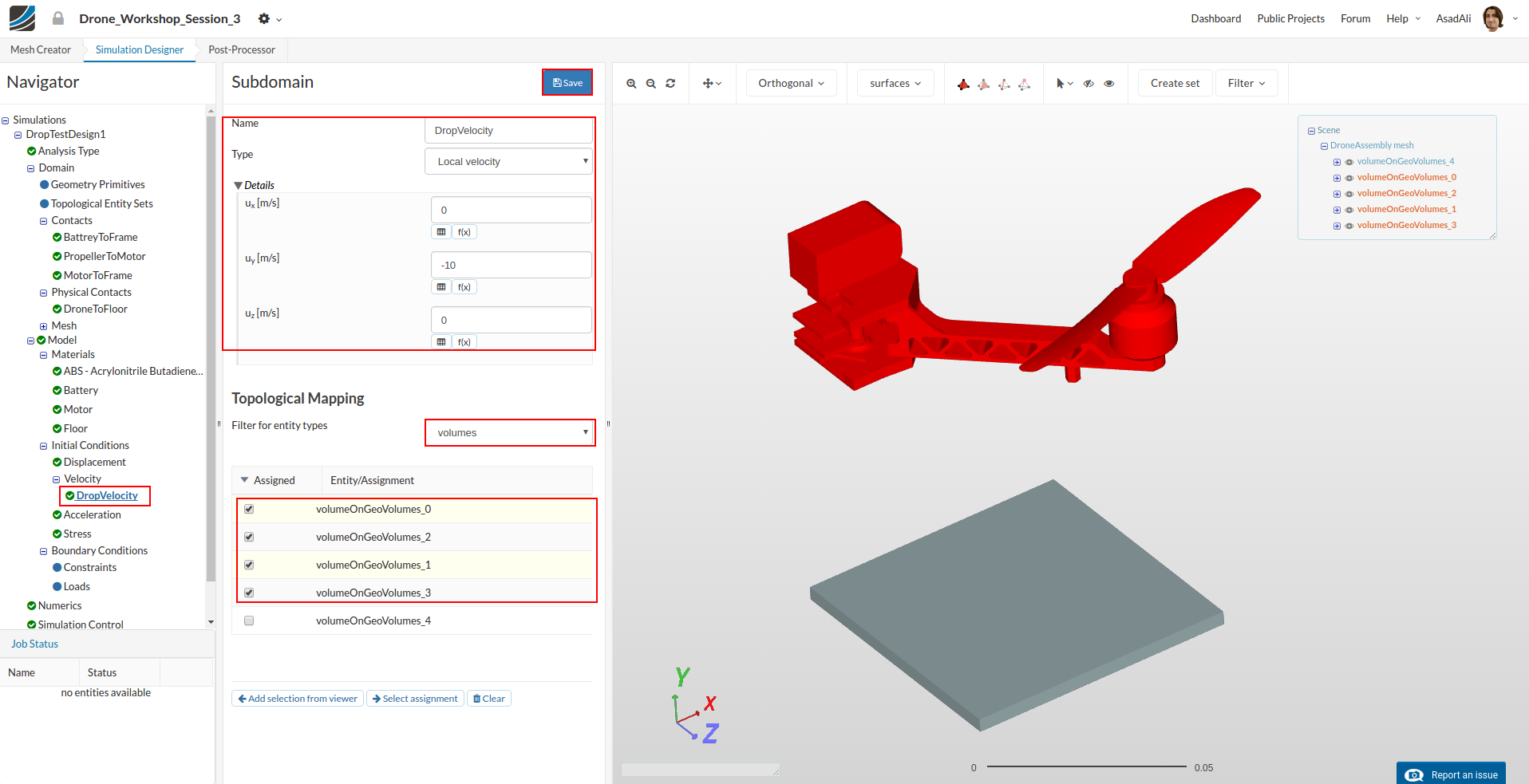
Since we only want to define the falling velocity of the drone (shortly before touching the floor), it is necessary to change the type for this initial condition to Subdomain-based.After saving this modification (1) , we are able to create a subdomain by clicking on New button (2).
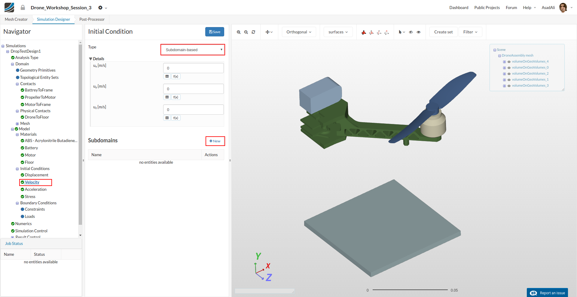
This will open a new middle column window where you have to define the following settings:
- Name: Drop Velocity
- ux: 0
- uy: -10
- uz: 0
Then map this condition to all volumes except the not moving floor.
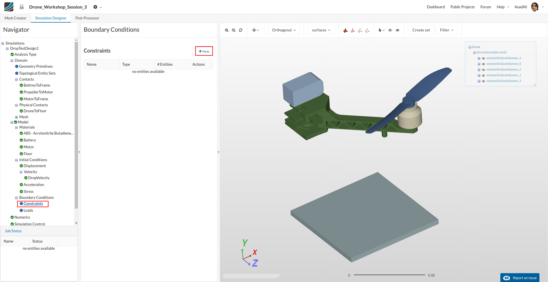
Under Boundary Conditions item in the project tree here are two kinds of boundary conditions for structural simulations.
- Constraint conditions are used to limit the degrees of freedom of the model.
- Load conditions are applying an external load to the model
Due the fact that there is now external load or force on the model, we only need to define three constraint boundary conditions.
To create a new constraint boundary condition please click on the relevant button in the middle column window.
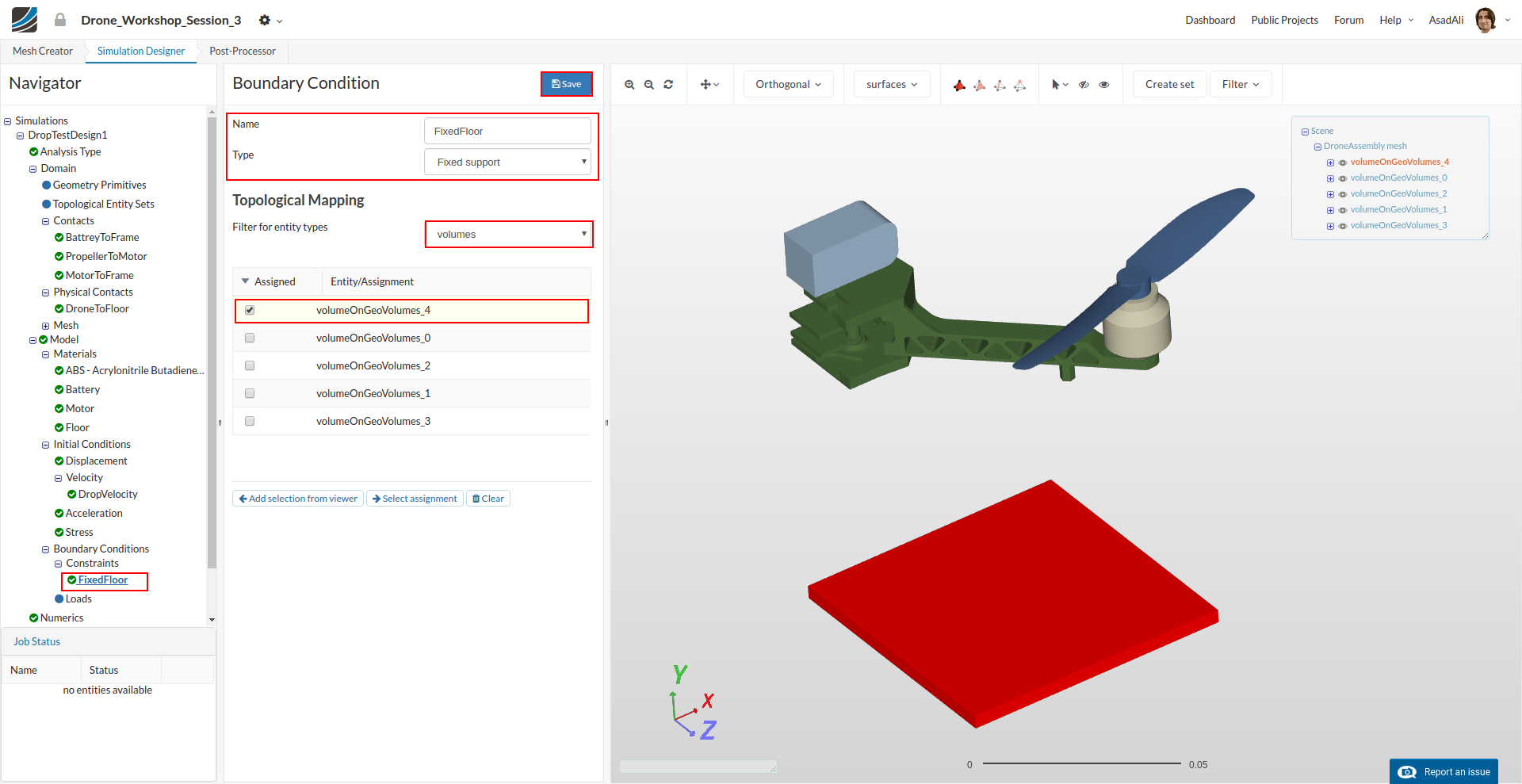
FixedFloor
The role of this boundary conditions is to fix the floor.
- Name: FixedFloor**
- Type: Fixed support
Finally, assign this boundary condition to the floor.
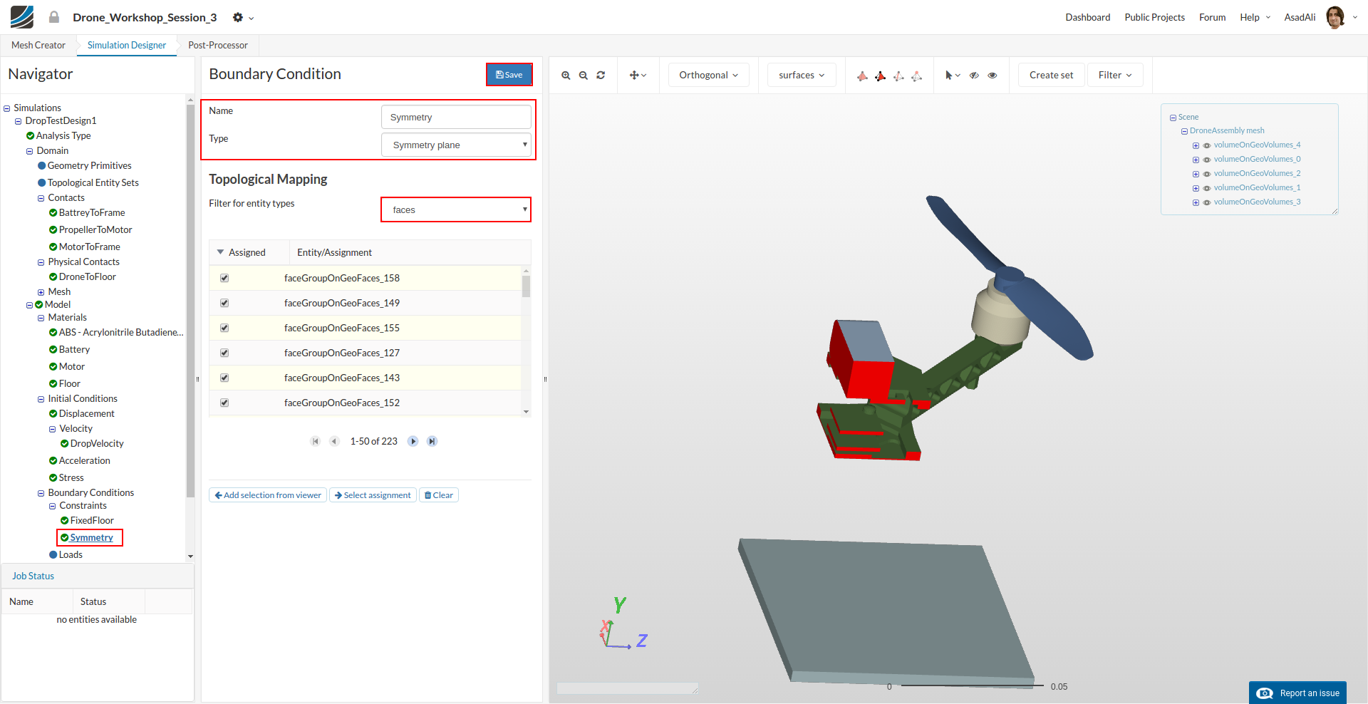
Symmetry
This boundary condition is required because we are using a quarter model of the drone.
Create a new constraint boundary condition by clicking on the relevant button.
- Name: Symmetry
- Type: Symmetry plane
Please assign all surfaces of the drone base plates which are bounding with the imaginary symmetry plane and therefore behaving like a symmetry plane.
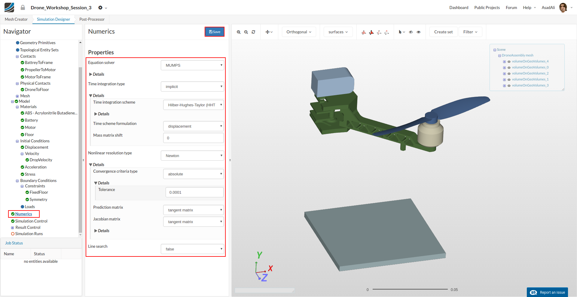
Next we will modify the numerical settings of our simulation to increase stability and speed. Click on the Numerics item in the project tree. This will open a new middle column menu where you can adapt the numerical schemes and tolerances:
-Equation solver: MUMPS
-
Time integration type: implicit
-
Time integration scheme: Hilb-Hughes-Taylor (HHT)
-
Nonline resolution type: Newton
-
Convergence criteria: absolute
-
Tolerance: 0.0001
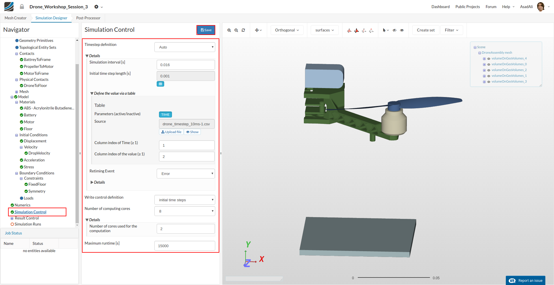
Click on the Simulation Control item in the project tree to specify how fast and accurate you want the simulation to be computed. Since we are running a dynamic simulation, we also have to care about the time step length.
The time step length can be comprehended similarly to the mesh size. It should be as a large as possible and as small an necessary. Due the fact that there will be only negligibly small stresses before the impact, we will use a large time step during the ‘free fall’ and a smaller time step before and during the impact.
- Timestep definition: Auto
- Simulation interval: 0.016
- Initial time step length: 0.001
Now click on the table icon under the field for Initial time step length.
This will expand the middle column menu. We will now upload a CSV file which describes the time step lengths for the different stages of the simulation. To download the file click on this link.
Click on the Upload file button and select the CSV file ‘drone_timestep_10ms-1.csv’. Make sure that you use Comma as the separator.
Finally change the number of computing cores to 8 and change the Maximum runtime to 15000
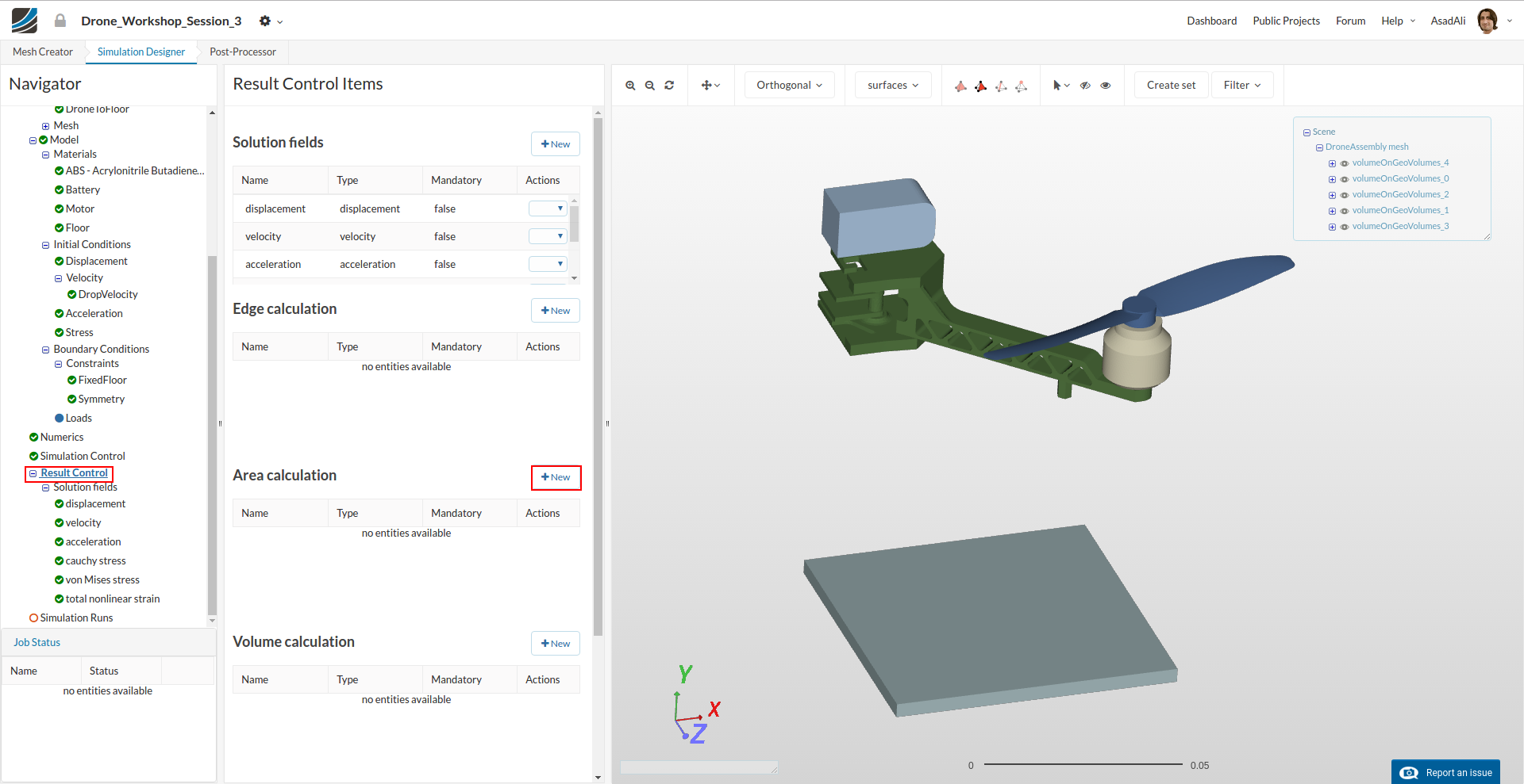
Click on the Result Control item in the project tree which will open a new middle column menu. Click on the New under Area calculation.
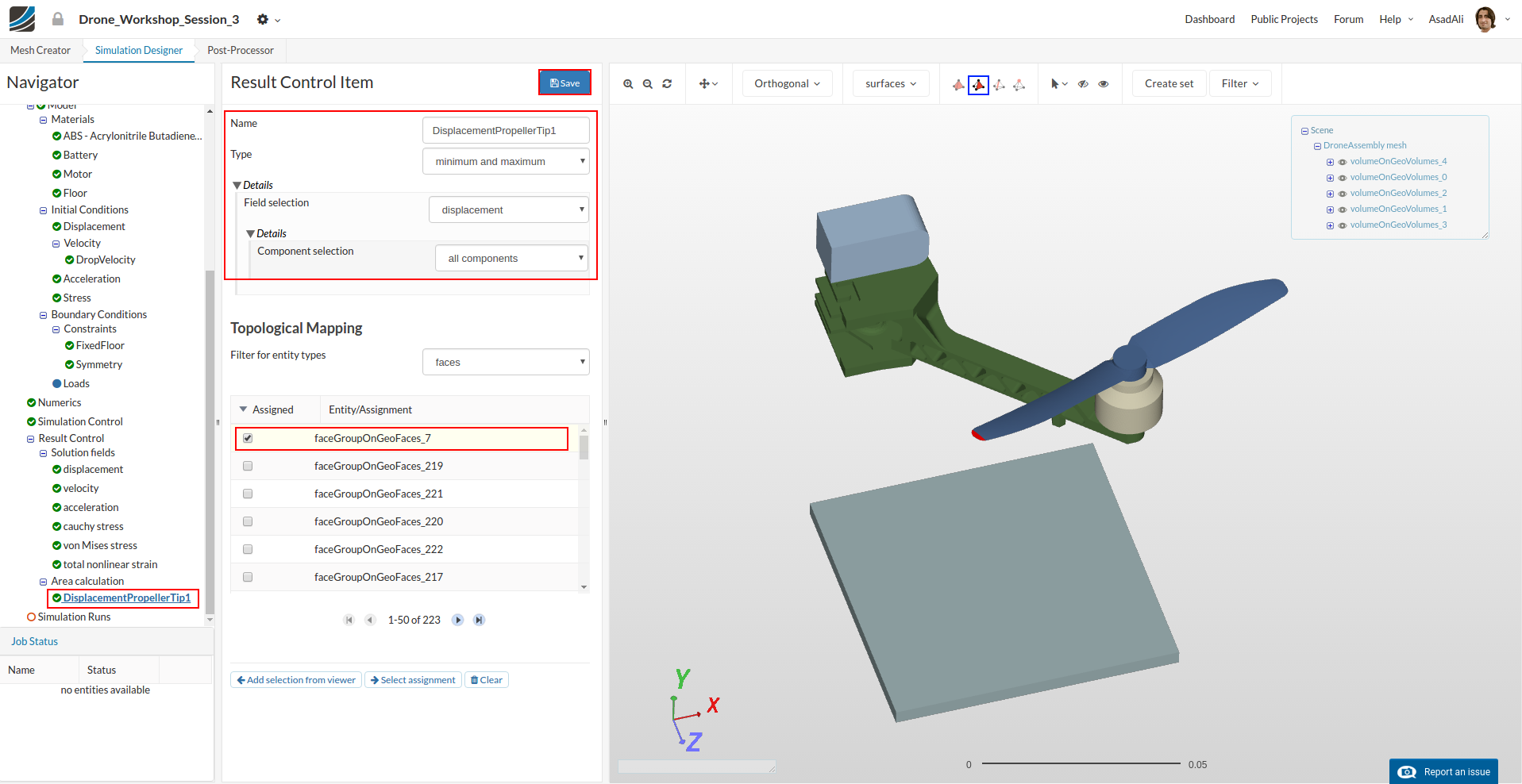
Now define the Result Control item as follows:
- Name: DisplacementPropellerTip1
- Type: minimum and maximum
- Field selection: displacement
- Component selection: all components
Assign the tip of the blade for this result control.
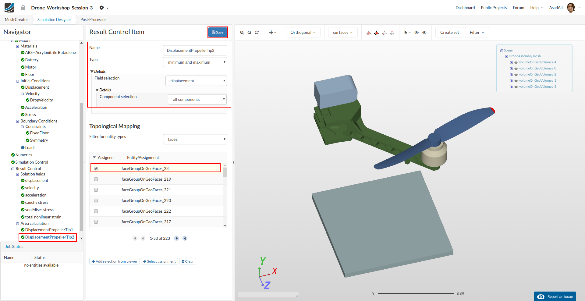
Add another Area Calculation result control and set the parameters as:
- Name: DisplacementPropellerTip2
- Type: minimum and maximum
- Field selection: displacement
- Component selection: all components
Assign the tip of the other blade for this result control.
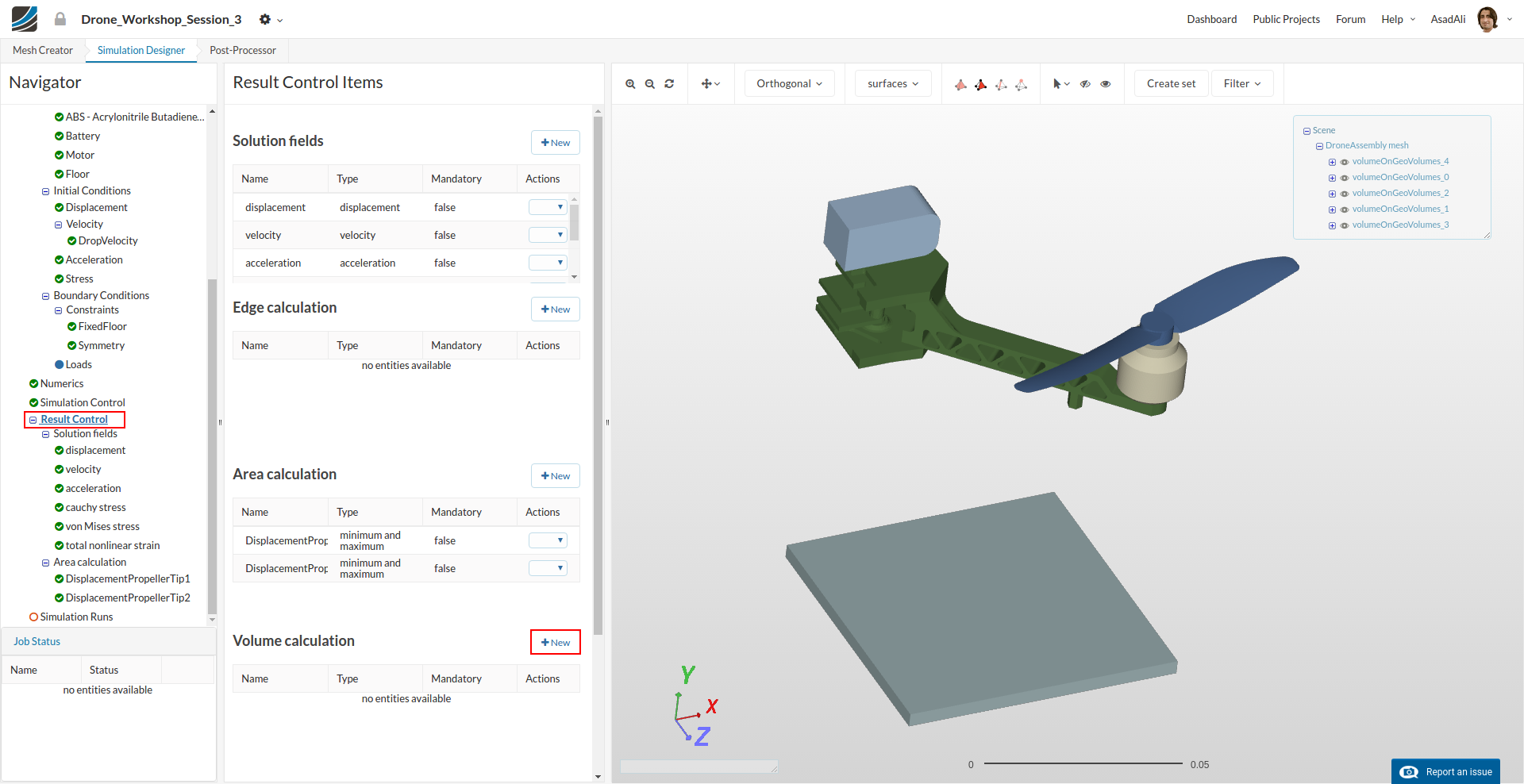
Finally we will add a Volume calculation result control item to get the highest stress in the drone chassis.
Create a new result control item by clicking the New against the Volume calculation item.
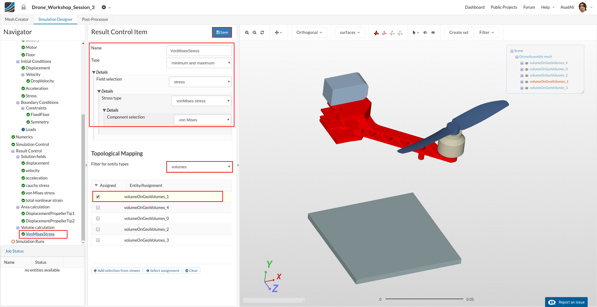
Now define the Result Control item as follows:
- Name: VonMisesStress
- Type: minimum and maximum
- Field selection: stress
- Stress type: vonMises stress
- Component selection: von Mises
Map it to the volume of the frame.
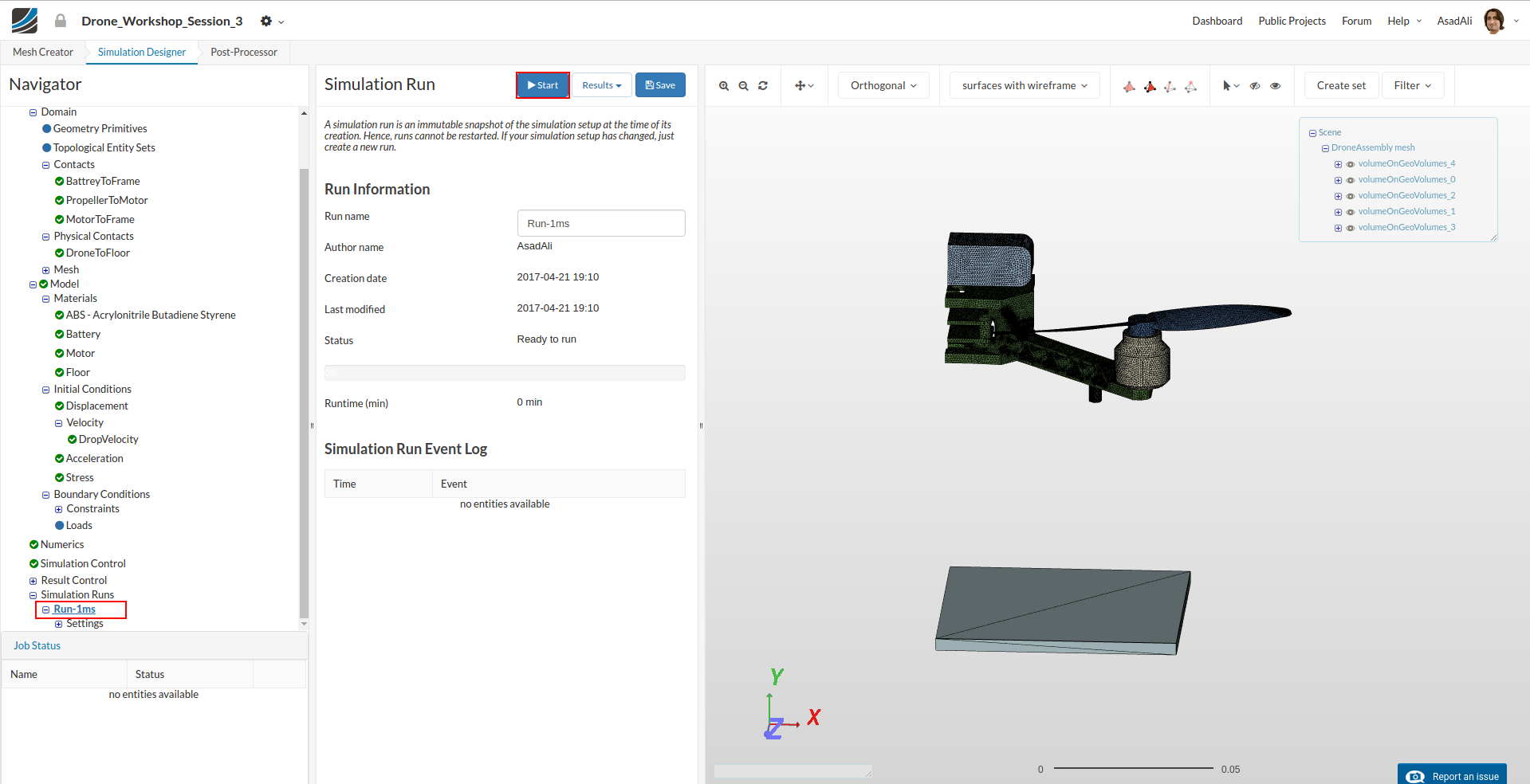
To start the simulation, click on the Simulation Run item in the tree and click on the New button at the bottom of the middle column menu. This will create a snapshot of your simulation settings as a new sub-item.
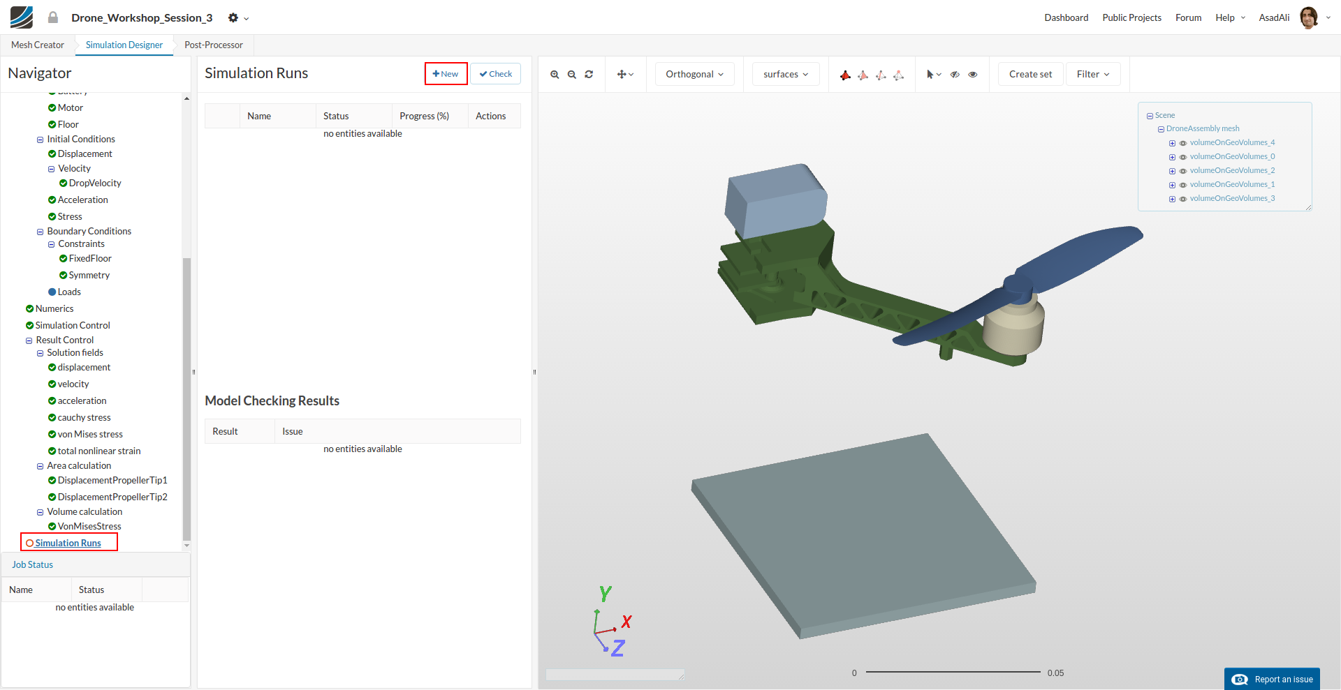
You can now start the simulation run by selecting it from the project tree and then click on the Start button.
Important note
It is not necessary to set up the simulation from scratch in order to simulate the other 3 falling velocities. You can just modify your simulation and create a new run. Since this is a dynamic simulation, you should make sure to update the following settings.
- To adapt the falling velocity you have to modify the initial conditions for velocity.
- Since a different falling velocity will impact the duration of the drop test, you also have to update some settings in simulation control.
- You have to change the Simulation interval to the according value as stated in the section above.
- You also have to use a different CSV file for time step length which you can download in the same section above.
Once your simulation is finished, please click on the Post-Processor button in the main ribbon bar.
Post-processing
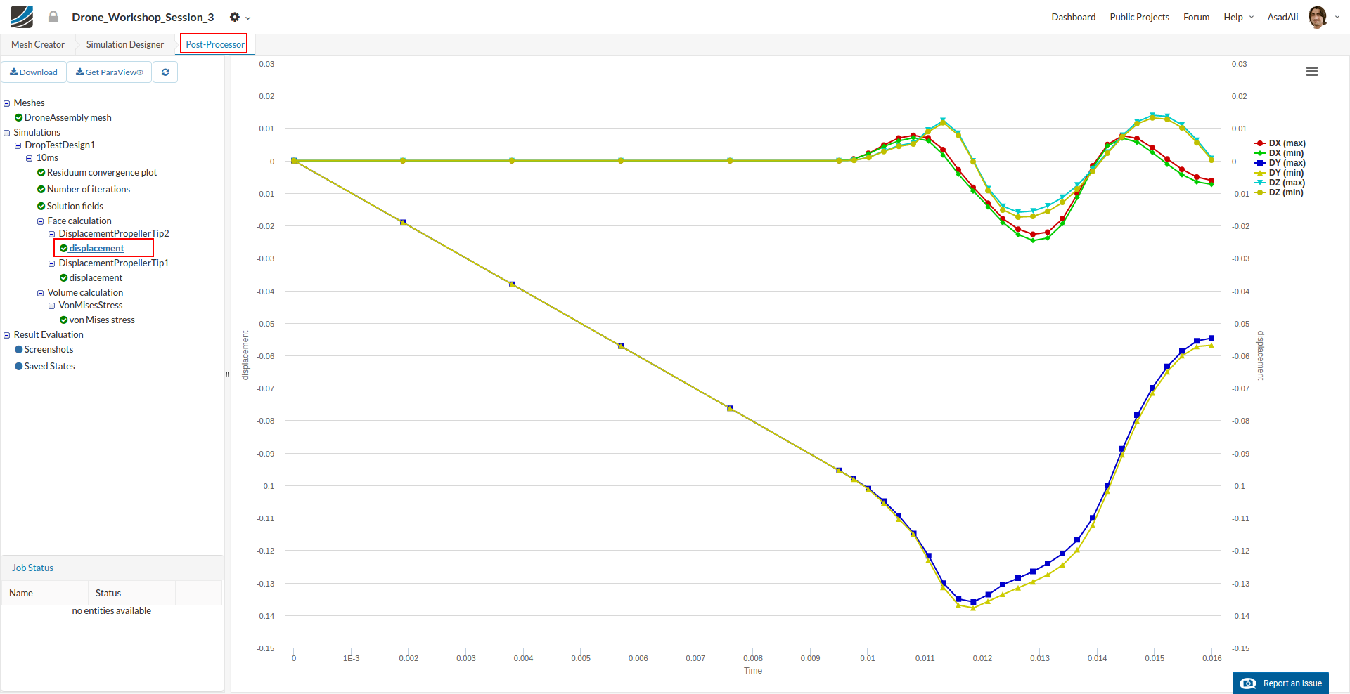
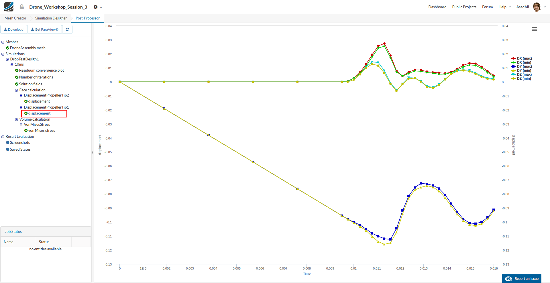
Once the simulation completes, move to the Post-Processing tab. First of all, we will take a look at the Result Control item we added.
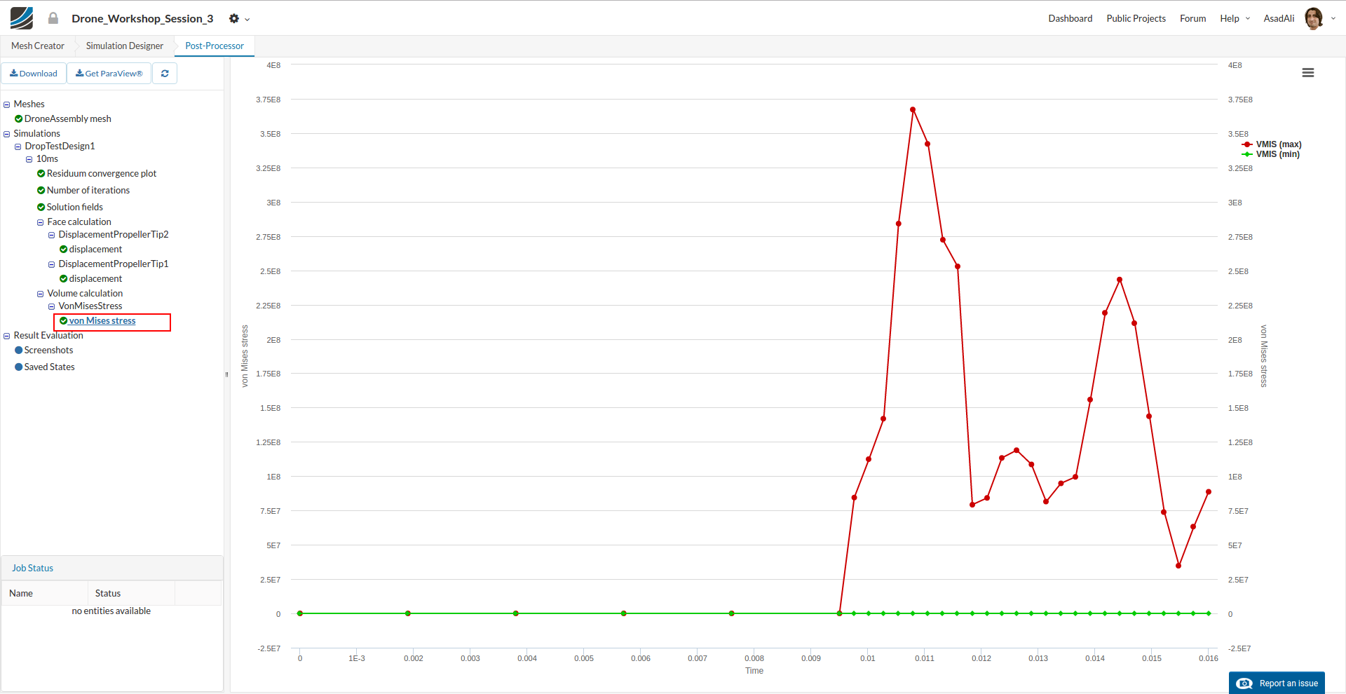
Clicking on the lowest elements of this tree will show you the plot of the relevant result control item.
The graph shows the maximum von Mises stress in the drone frame versus the time.
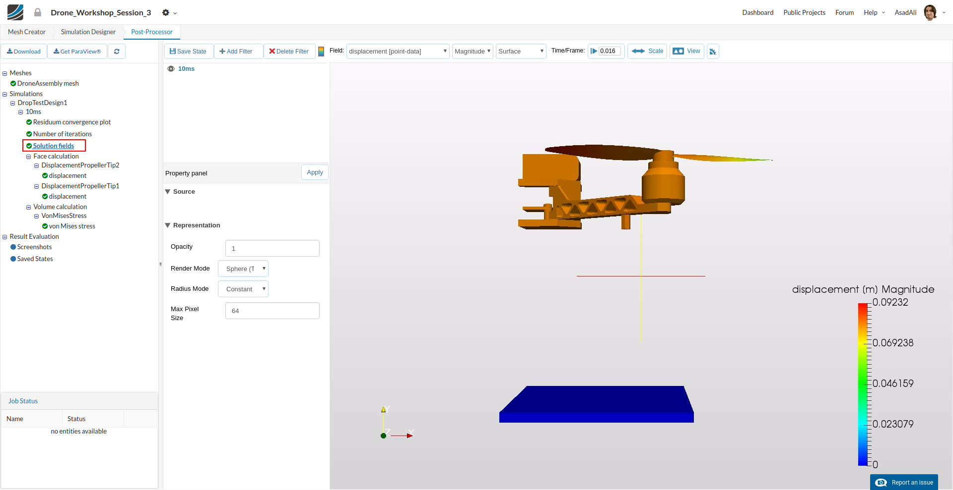
Next we will take a look at the 3D result. Click on the Solution fields in the project tree.
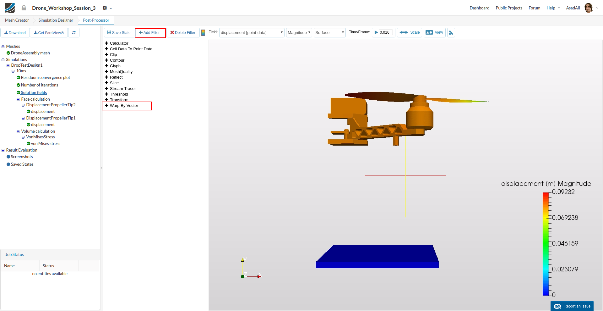
Click therefore on the Add Filter button and choose the WrapByVector filter from the list.
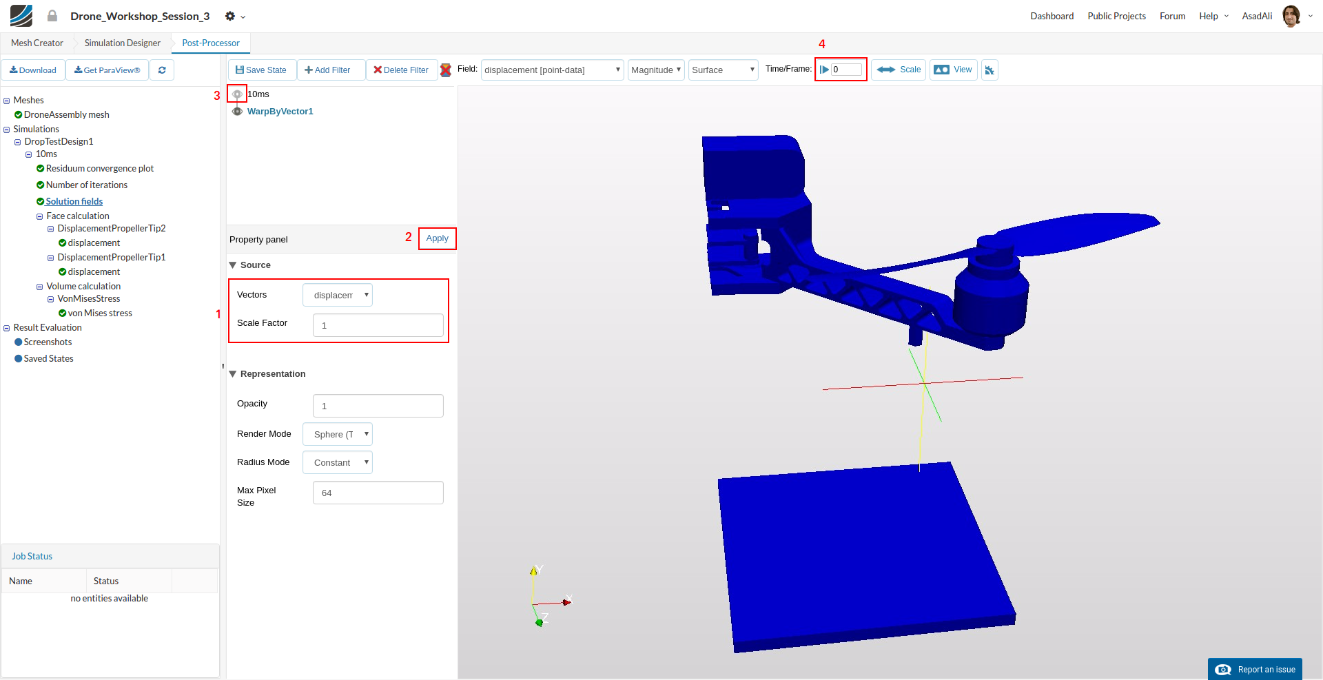
In the Property panel, you can define which Vector field you want to visualize and define as:
- Vectors: displacement
- ScaleFactor: 1
And press Apply. Hide the original solution by pressing the eye button next to it. You can also change the plotted time of the simulation.
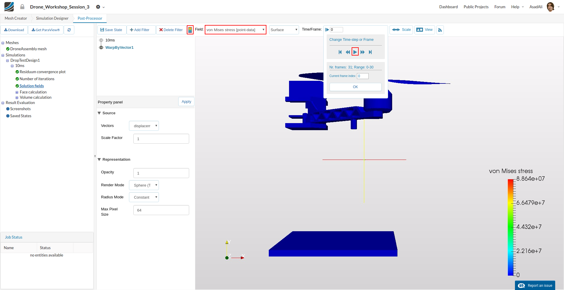
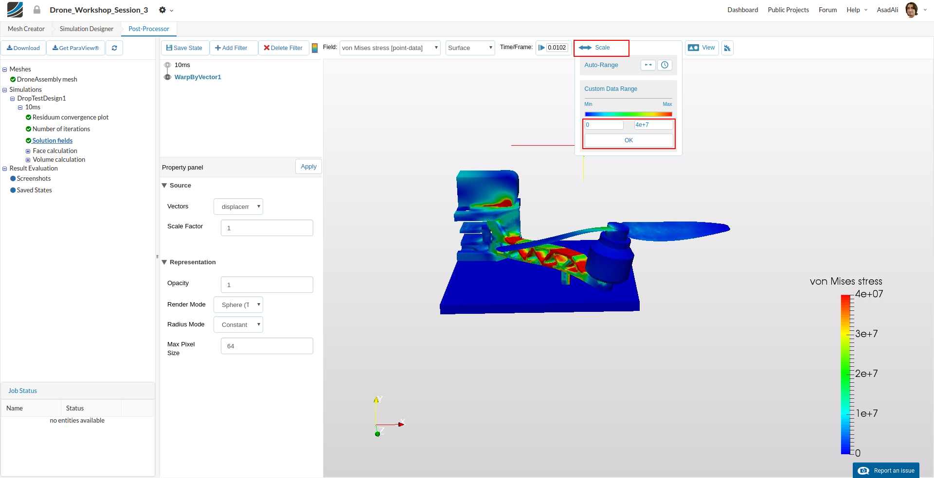
Next change the field representation to vonMises_stress. You can hide/show the colorbar by pressing the relevant button. Now you can see the simulation drop dynamics by pressing the relevant button in the Time/Frame
For better visualization you can change the legend color by pressing the Scale and changing the range of the displayed colors.
Congratulations, you have completed the Homework of Session 3