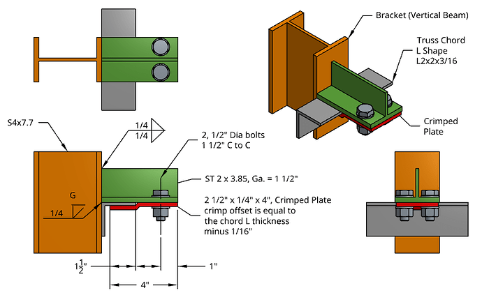
- Is the ST member only welded to the bracket? Please list all the welds, for each pair of members in contact. Answer: Yes, the ST member is welded to the Bracket. To simplify the analysis, we could assume that the ST member and the bracket behave like one part. Please see details below.
-
What contact face pairs are assumed to be bearing/sliding? Answer: The Truss Chord L Shape would act as the bearing face since it is partially in contact with the face surfaces of the ST member bottom flange and flange of bracket. Also, the crimpled plate (also known as the clamp plate) is in contact with the Truss Chord L Shape.
-
Is bolt pretension + friction to be taken into account? Answer: Yes, we could assume bolt pretension + friction. I prefer assuming the bolt type as N for Bearing bolt with threads included in shear plane instead of Slip-Critical (SC).
-
Can you please signal the continuity faces? That is, faces where members are cut to reduce the model. Answer: The model is at minimum and I which to keep the model at this size. The contact boundary conditions are in the diagram below (i.e. thick lines colored in blue).

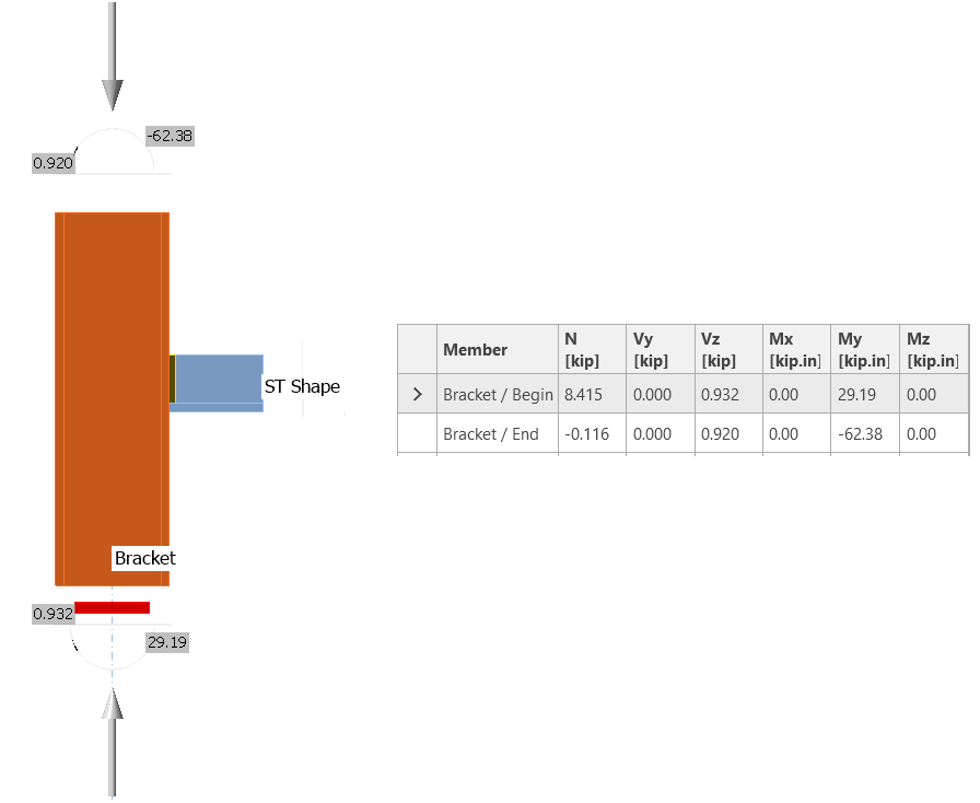
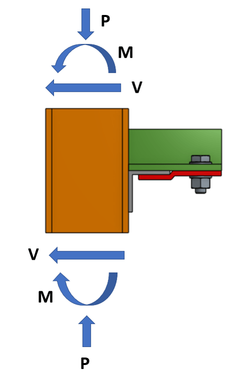
- Can you please list the loads in a table? Are they in balance? Answer: Yes, the loads are in balance and were taken from a structural analysis program (Post-Processing). The force unit are in kips for Shear (V) and Axial (N), and kips-inches for the Moments (M). See diagram and table below.