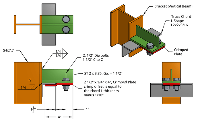
Hi, I am working with an academical project to model a steel connection to analyze the stresses along the different components. The issue I am getting is that the simulation is not converging due to boundary conditions issues (i.e. contact surfaces between different parts). The purpose of the model is to analyze the behavior of a shear steel connector attached to a quad-chord truss (L-Shape L2x2x3/16), especially, to determine the tension at the bolts (1/2" diameter) due to prying action and to determine the stresses at the ST shape. The ST2x3.85 member is welded to the bracket (vertical beam. S4x7.7). The loads considered are dead loads (DL) and wind load (WL) and are inputted in the model.
Please see below other details relevant for the simulation.
Definitely your simulation setup doesn’t correspond with the model you describe. I will help you to get there, but before that happens I need a few more details:
Is the ST member only welded to the bracket? Please list all the welds, for each pair of members in contact
What contact face pairs are assumed to be bearing/sliding?
Is bolt pretension + friction to be taken into account?
Can you please signal the continuity faces? That is, faces where members are cut to reduce the model.
Can you please list the loads in a table? Are they in balance?
Is the ST member only welded to the bracket? Please list all the welds, for each pair of members in contact. Answer: Yes, the ST member is welded to the Bracket. To simplify the analysis, we could assume that the ST member and the bracket behave like one part. Please see details below.
What contact face pairs are assumed to be bearing/sliding? Answer: The Truss Chord L Shape would act as the bearing face since it is partially in contact with the face surfaces of the ST member bottom flange and flange of bracket. Also, the crimpled plate (also known as the clamp plate) is in contact with the Truss Chord L Shape.
Is bolt pretension + friction to be taken into account? Answer: Yes, we could assume bolt pretension + friction. I prefer assuming the bolt type as N for Bearing bolt with threads included in shear plane instead of Slip-Critical (SC).
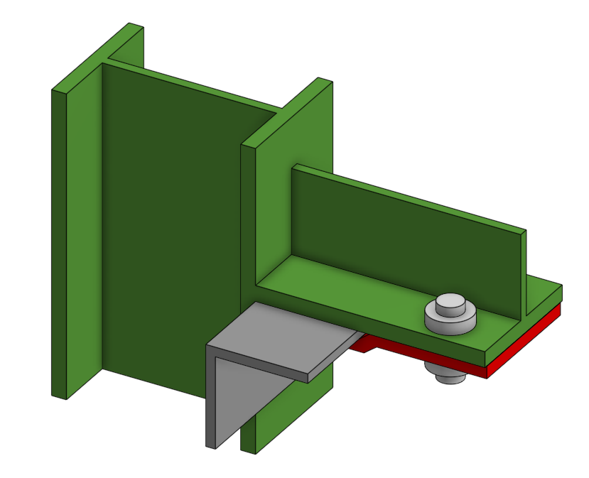
Can you please signal the continuity faces? That is, faces where members are cut to reduce the model. Answer: The model is at minimum and I which to keep the model at this size. The contact boundary conditions are in the diagram below (i.e. thick lines colored in blue).
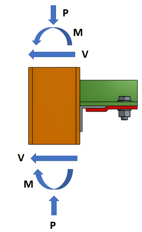
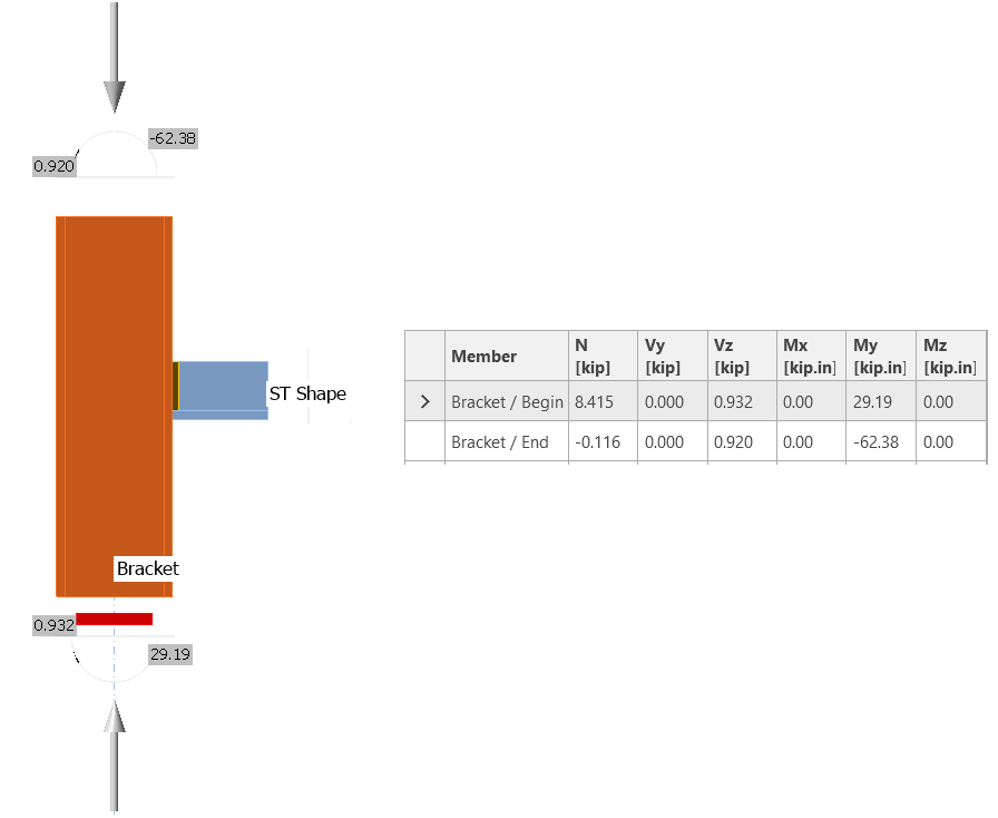
Can you please list the loads in a table? Are they in balance? Answer: Yes, the loads are in balance and were taken from a structural analysis program (Post-Processing). The force unit are in kips for Shear (V) and Axial (N), and kips-inches for the Moments (M). See diagram and table below.
I can see from the load table that the forces do not balance to zero. This makes it difficult to apply the boundary conditions, because if you fix one end and load the other, you won’t get the same scenario.
Please search for the remaining loads that will make the structure to balance, perhaps on the chord or on the beam. Then you can simply fix say the bottom face and apply all the other loads.
The bear surfaces (blue lines in your figure) can be modeled with sliding contacts, or with physical contacts (optionally with friction) if you move up to a non-linear simulation.
Also, please add the bolts, at least with a simplified geometry, to be able to add the bolt pretension effect.
The loads are correct. The loads at the top face of the bracket are based on cantilever loads due to wind loads. The loads at the bottom are due to interaction between other structural elements (other truss elements involved).
To simplify further the loads on the model, I am willing to only include the cantilever loads at the top face of the bracket. That is the wind load moment of 62.36 kip-ft, wind shear load of 0.92 kips, and dead axial load of 0.116 kips (Per the table on previous reply).
This model is basically a “clamp” connector of the bracket attached to the truss chord L Shape. Technically, the fixed supports shall be the two cross sectional faces of the chord L Shape. In the model these two faces were assigned as “fixed supports”.
I prefer modeling the boundary conditions as physical contacts with friction. That will be the real case.
As requested, the bolts are included in the model. Please, for the analysis, refer to Static Rev01 (With Bolts). For the geometry, refer to Assembly_3 (With Bolts). Please note that the bracket and the ST member are merged to one part.