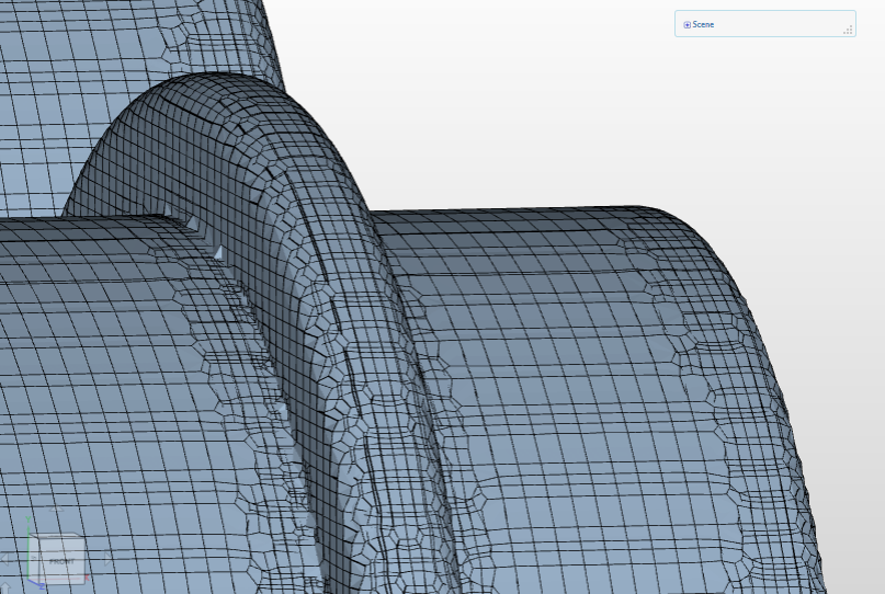
Hi @Naly, can you put a link up? If you increase the refinement level are you left with smaller ‘steps’ just wondering if it is mesh or geometry. If it is mesh, I usually have some jagged edges:
This is a setting that allows you to control the minimum cell size you want the mesher to generate. Just do a test and put it to a very small value to see if it helps.
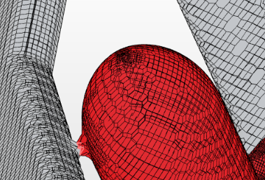
Hi, David, yes for most of my cases the shape is too complicated to lay cylindrical refinements along the edges. For this case, however, the prop is all one surface with no edges.
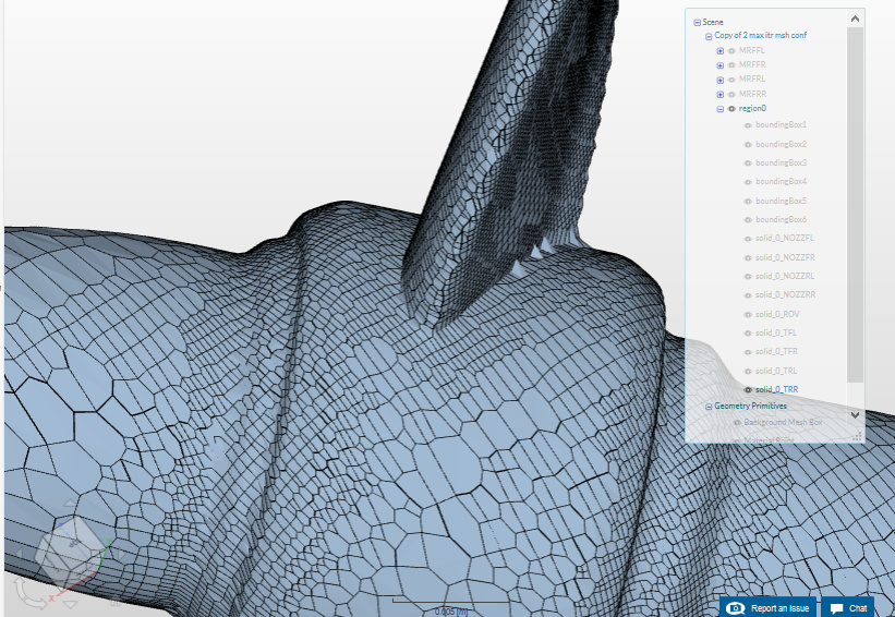
So far due to the size of the mesh (and my connection), I have been unable to look at the mesh however, I think you above solution looks more likely to be the issue, my edges are jagged, but at least they stick to the shape. On Naly’s it looks like cells have been cancelled near the face. Think this model would be much easier to manage if there were more faces to control.
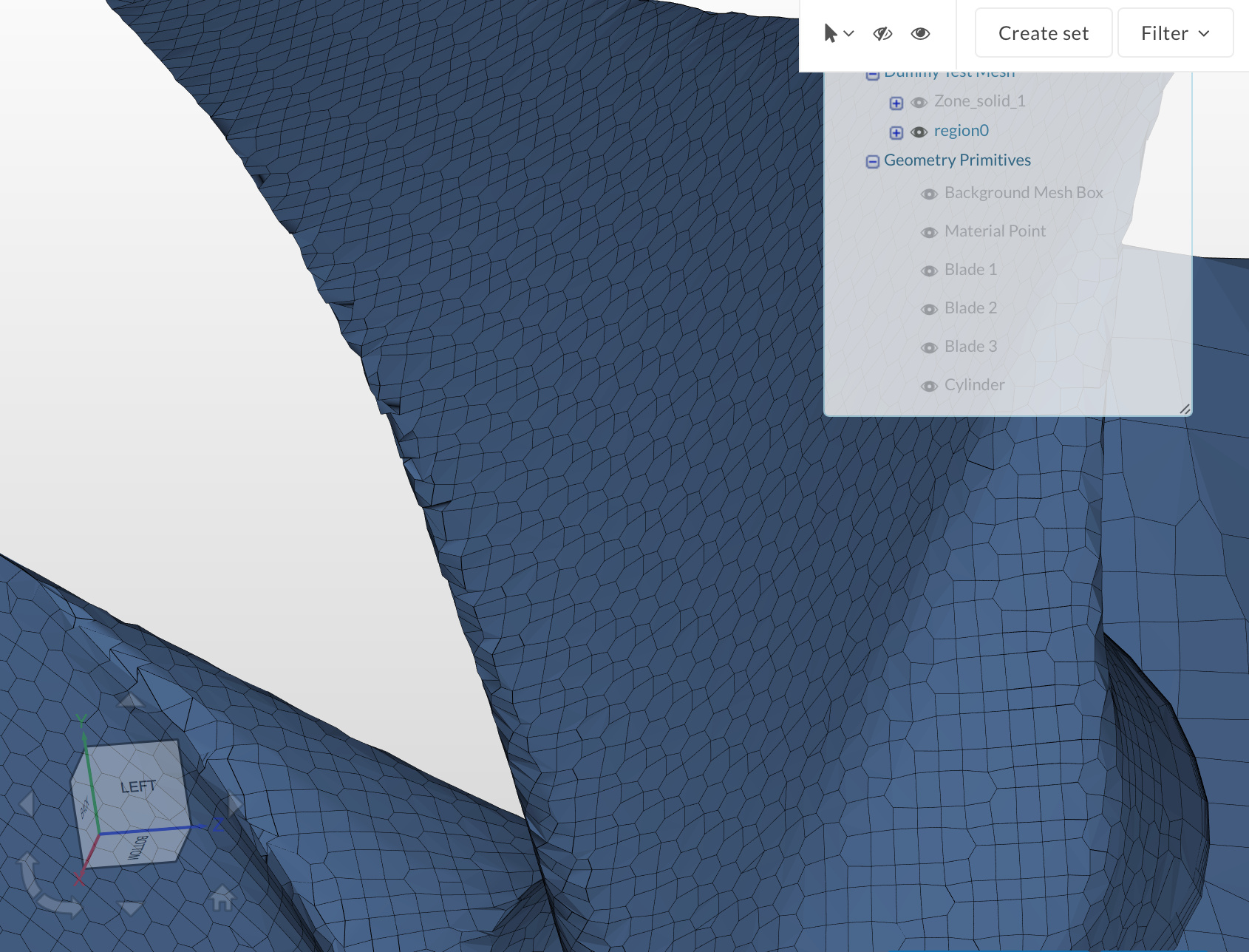
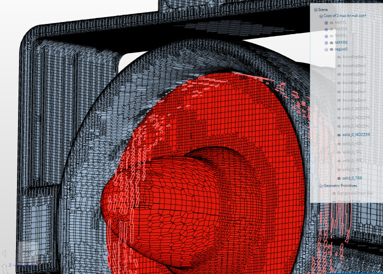
Since rotation zones are very close to the nozzles, one of the MRF zones fails:
error: “Creation of the following cell zone might not succeed. Assigned entities are not closed: MRFRL”
Hi, @Naly, you could try completely disabling the check by putting a large negative number in (I think there is a recommended value in the docs of something like -1e30) this might fix a fair few issues.
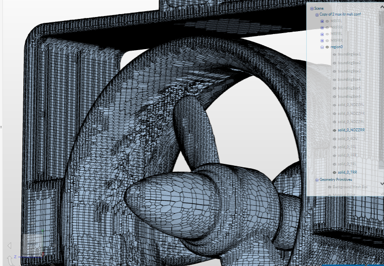
If the faces were split (i.e. the faces of the blade were split from the centrepiece) then we could use feature refinements to more effect, (and later edge refinement as suggested by David above) this might end up sorting the faces merging inadvertently, that said the most controlled method to stop this happening would be to insert a cylindric primitive on the blade tips and refine them.
As for the MRF failure, we could split the faces and refine the outer surface the issue here again might be merging with the duct?
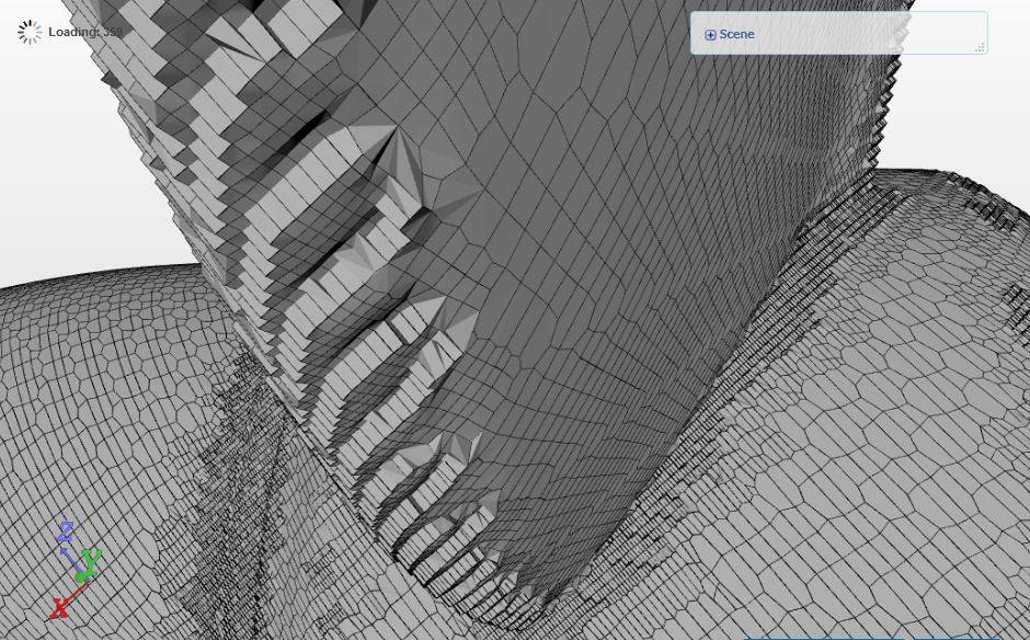
Hi @Naly, your pictures seem a bit strange. Looks like two overlapping meshes. This can happen when your stl is not watertight, so the mesh “goes inside” the model, meshing both positive and negative faces of the geometry. Anyway, why do you think that the mesh on your first and second picture is bad? You are trying to mesh a curvature with one or two cells, and it will never be smooth.
I have also observed, that smoothing with 100 iterations gives better results and less errors than 300 (what Simscale recommends). Lowering the minVol parameter is the solution to add very small cells to the mesh, but usually it will introduce more errors. I don’t know either what OF version Simscale is using, but the latest 1706 is much better and faster in meshing.
I hope this helps!
Attila