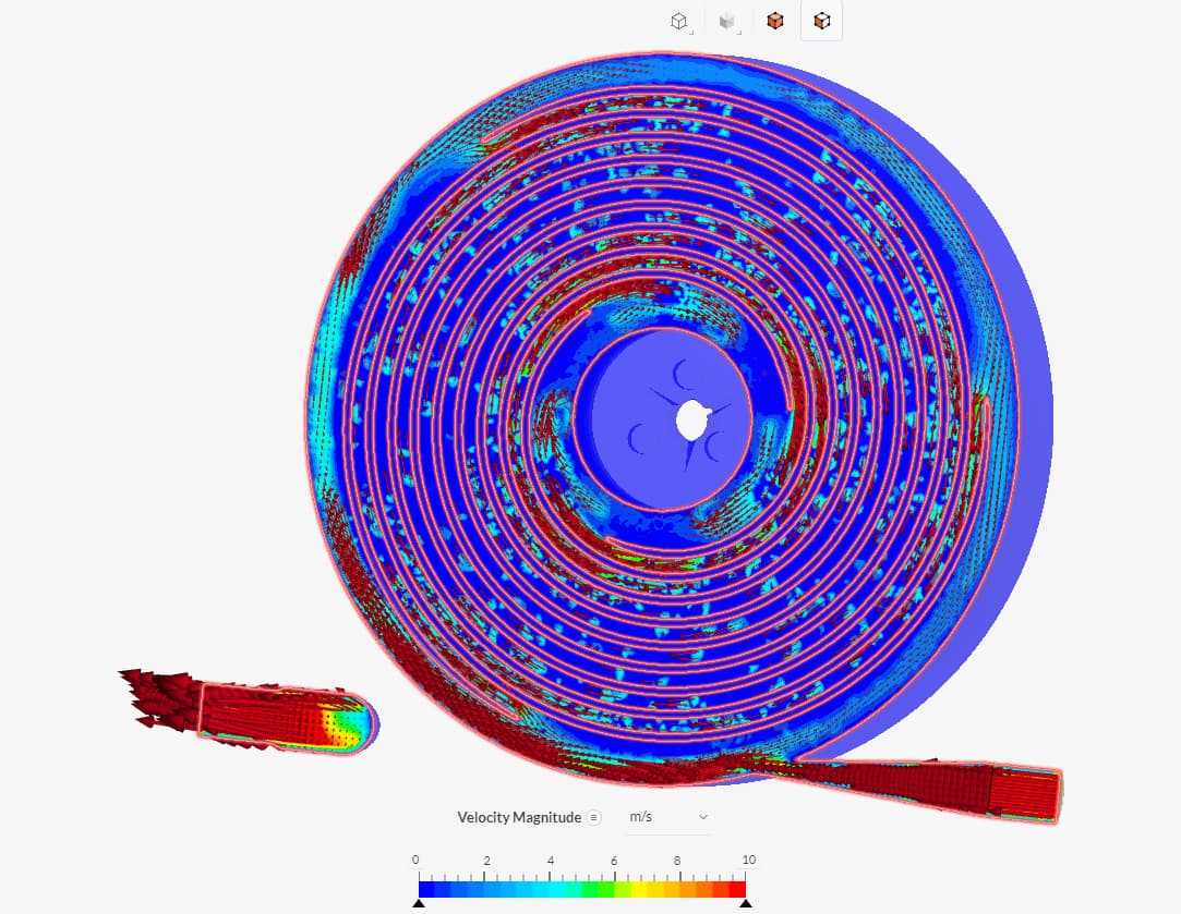
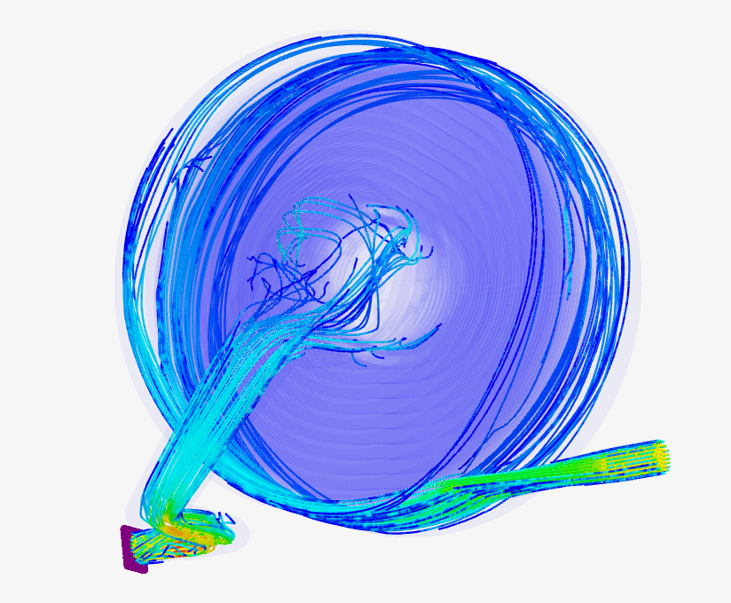
Hello Everyone. I’m trying to get my particle trace to enter the spiral paths in my flow volume. It either won’t show the particle paths, or it doesn’t enter the spiral path in the simulation at all.
(Flow Sim Results. Particle trace on both the exhaust and inlet. Missing particle trace in spiral paths):
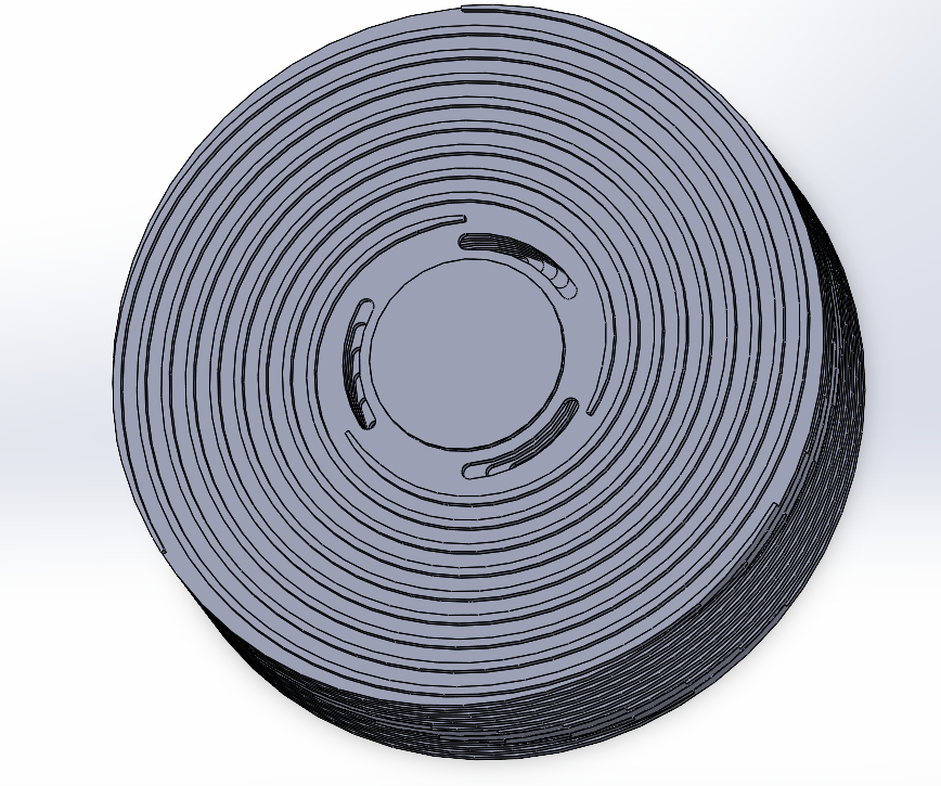
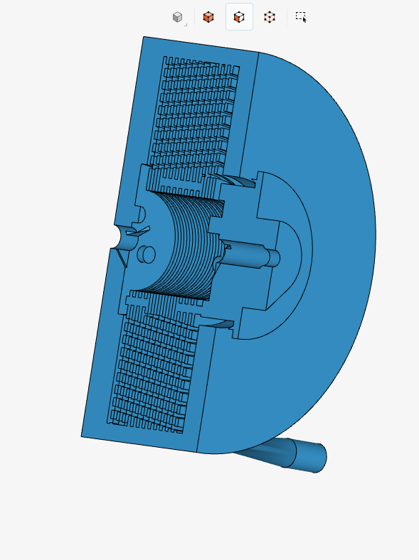
I have designed a modified Tesla Turbine in which the disks have Archimedean spiral engravings leading from the outer permitter of the disks into the central exhaust holes. The idea here is that by forcing the air to take a longer path, the air will cover a greater surface area and produce more drag from the boundary layer effect.
(Example of 12 Disks Stacked. 10 degree rotation between each disk):
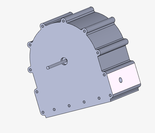
Here is the casing with the disk stack inside.
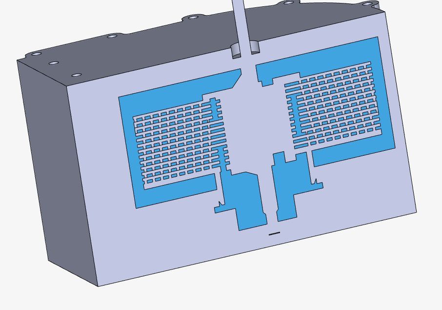
Here is a cross section.
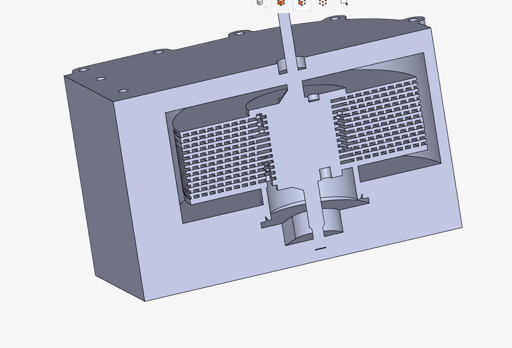
I use the internal volume flow tool in the SimScale cad editor and I get a good flow volume. All of the empty spaces are connected and there is a complete path from the inlet to the outlet.
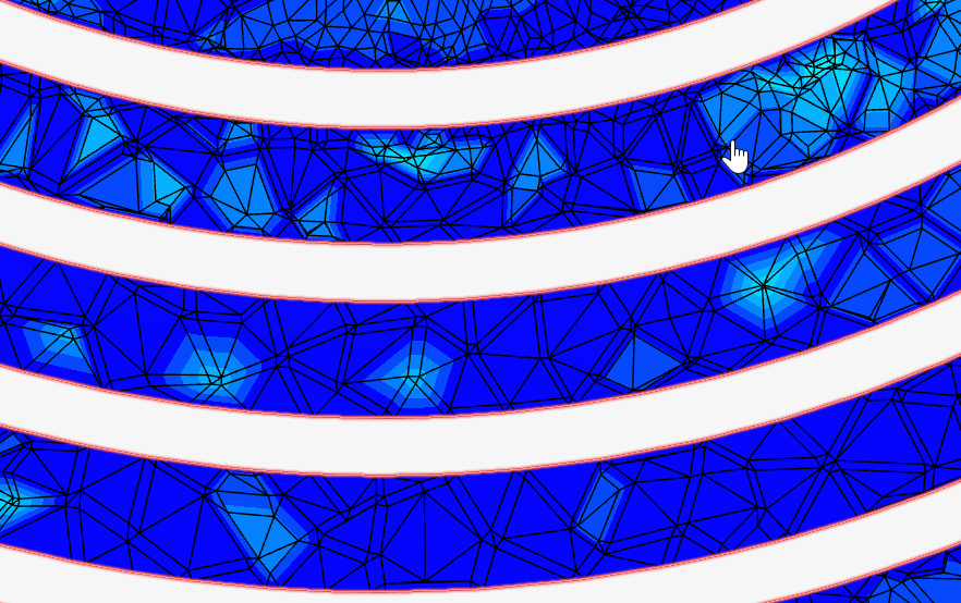
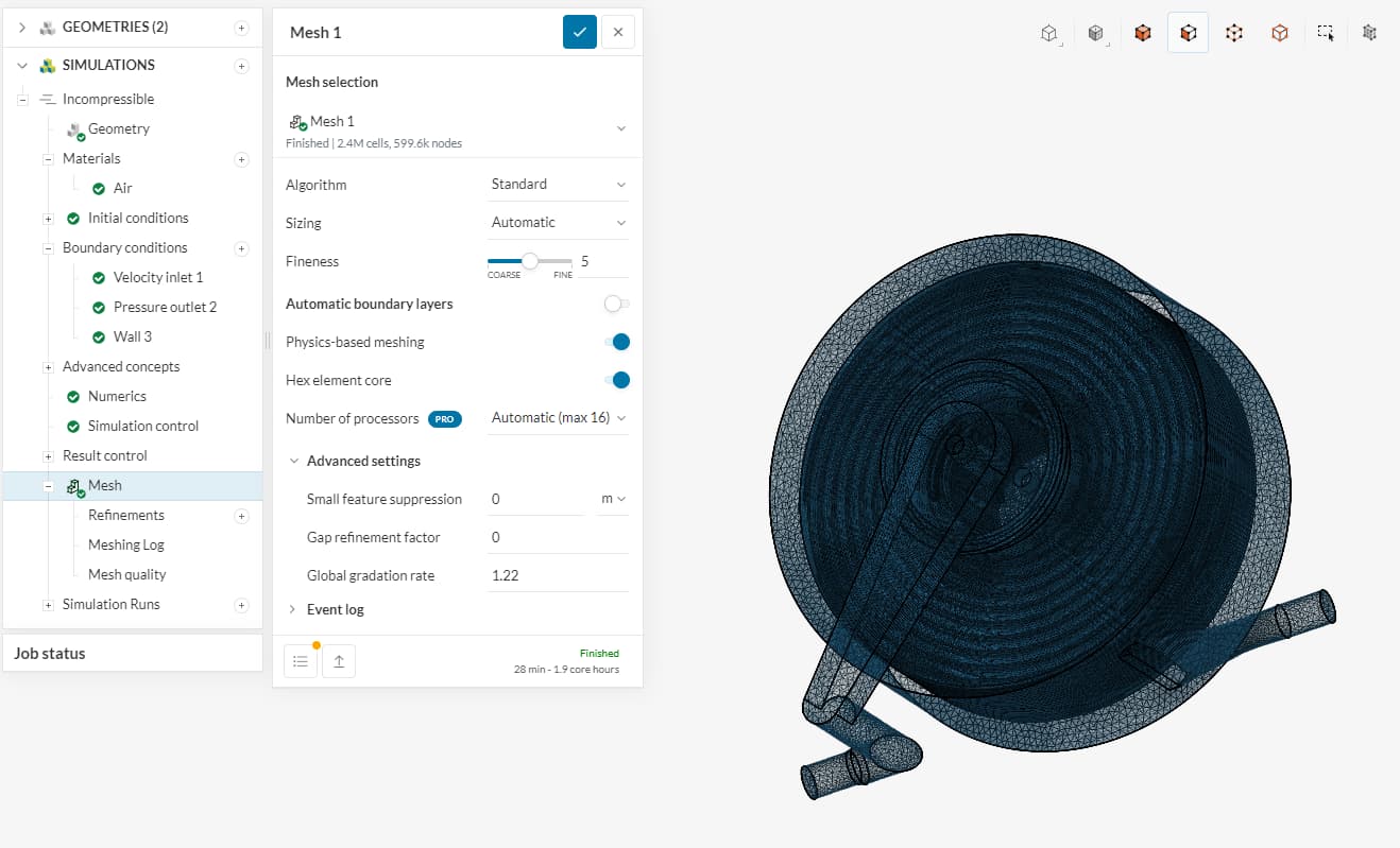
Here are my Mesh Settings.
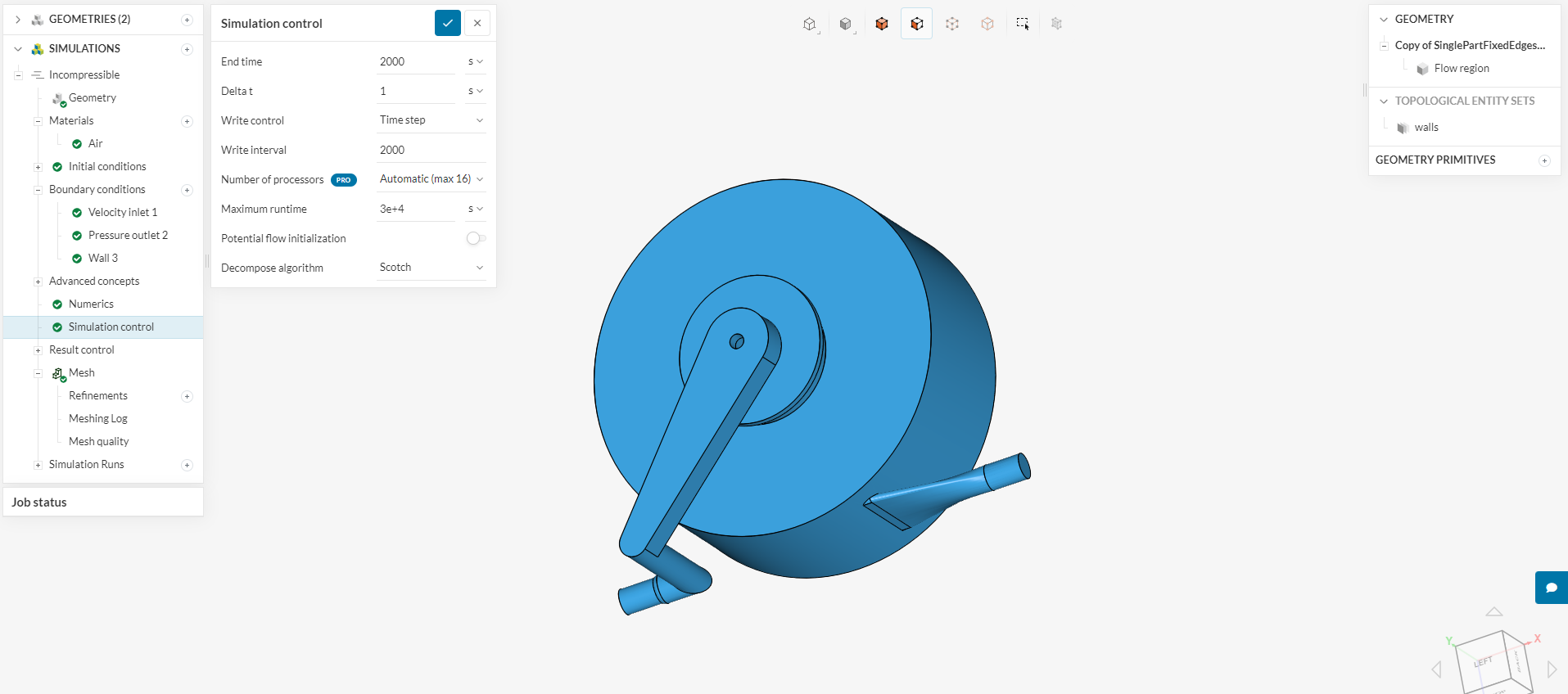
Here are my Simulation Settings.
As I said at the top, I just want to show the path the fluid takes from inlet to outlet.
There is no Rotating Zone in this simulation.
Could it be a problem with my mesh? I am only a hobbyist so I’m not that experienced.
The purpose of this simulation is only to produce a cool visual. It should look like a tornado, with air entering the perimeter of the disks, spiraling inward, and converging in the central exhaust. The specific conditions of the simulation don’t really matter.
Any advice would be appreciated. Thanks!
Project Here: