Solution Run stopped because of error

Subject: Solution Run stopped because of error

Greer Scarborough

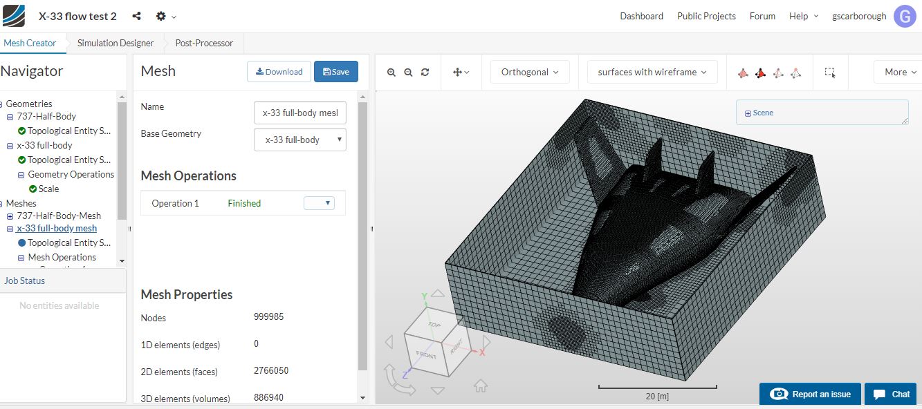
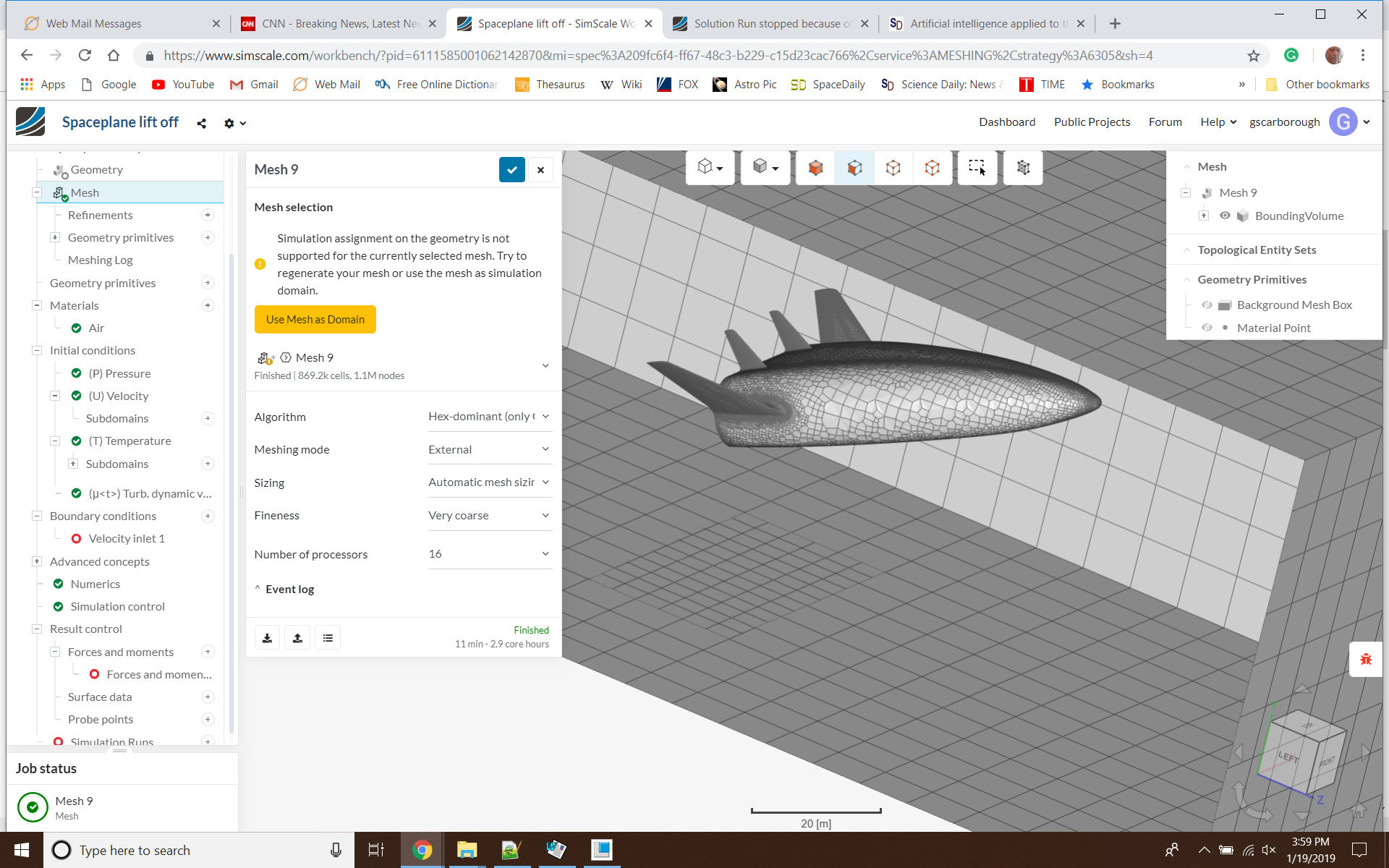
I am trying to model the aerodynamics of the X_33 spaceplane taking-off. Currently, I have a CAD model of x-33 from the internet in the middle of the virtual wind tunnel. I used the Simscale project: Airflow around a Commercial Aircraft - Aerodynamics Analysis by Ali_Arafat | SimScale
as a starting point; same material, properties etc. However, It did not run maybe because I should have used only half of aircraft and a symmetry Boundary Condition or different Velocity residual control, absolute tolerance or Simulation control settings. I need some help solving these problems.

Thank You
Greer Scarborough
Mobile 805-2363459

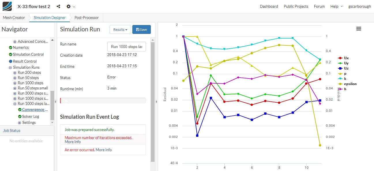
Solution Run for X-33 model stopped because of error, no results:
maximum number of iterations exceeded, runtime 3 min

I don’t understand which way the residuals are supposed to converge.
It looks like epsilon (whatever that is?) is getting smaller,
which would seem better. However, When my pipe model solved
the residuals converged towards the value of 1. Did they get larger and better?
I don’t think I understand what is happening with these residuals.

In stress analysis, the convergence is when results become constant
even though the size of the mesh is getting smaller. Are we talking about
the same thing with SimScale convergence?

Epsilon diverging in Convergence plots (residuals graph):
at 11 seconds epsilon had the value of .0012 when the run ended

Simulation control:
end time 1000, write interval (time steps) 50, max runtime 9000

Numerics:
Velocity residual control, absolute tolerance: 00001
Epslion residual control, absolute tolerance: .00001

Should I make these tolerances smaller or larger?

Thank You,
Greer Scarborough
Mobile 805-2363459

1 Like

Hi @gscarborough!

Just a quick first tip for you. Increase the size of the fluid domain! A good example can be found for other aerodynamic projects in our project library. That should help! Please tell us how it went and if you still have problems we will jump in to help you!

Best,

Jousef

1 Like

I got some new CAD software, Creo 5.0 , so I could be able now to create solid model that is more reliable, that willnot have gaps between surfaces. I think the new model should solve when I have a finer mesh, unlike before. I have some simple basic questions;

  1. How do you save project so you don’t loose the mesh and other data. How do you know it has been saved.

  2. I am modeling and aircraft so I created a box to simulate a aerodynamics test chamber and used a external flow. I would then select inlet and outlet by selecting box surfaces. Is that the correct procedure for the new meshing procedures?

Sincerely,
Greer Scarborough

New project is named Spaceplane lift off.

I succeded in creating a coarse mesh, however could not select inlet of flow. When I tried to create the boundary conditions by selecting inlet, only the aircraft was shown. The boundary box was not shown, so I could not select the velocity inlet as I did before.

Greer Scarborough

Hi Greer!

  1. It automatically saves your data - however I never tested if you loose your connection for a short amount of time but once it reconnects everything should be fine

  2. Usually you upload your model without an already existing bounding box (for some cases it might make sense though) and make sure that you create a domain size that is big enough as previously mentioned. External flow simulation is the correct option for this. If you have problems a screenshot of the issue would help.


You have to make sure the mesh finished meshing otherwise you cannot use it for the simulation! Also care about your CAD model: “The tesselated surface is not closed. There could be a problem with the CAD geometry (such as self-intersections). Please inspect your geometry. Trying to proceed anyway.” It means exactly what it says, so if you have some model issues fix them before running a mesh - else you are going to have a bad time.

I am here to help if you need anything, just ping me :slight_smile:

Best,

Jousef

Project: Spaceplane Lift off

I am not sure if I succeeded in creating a mesh. I see elements on the aircraft and box (box is boundary of mesh?) but not in between. The program said: Run creation failed because mesh has not been generated yet. I guess this means there is no mesh. Is the bad CAD geometry causing an error in creating the mesh which is why I cannot create a run? Did I succeed in creating a proper 3D mesh?

Should I select the surface (face) on the box in front of aircraft for velocity inlet? The box is not visible when I try and select it, when the “boundary conditions” function is running. Cannot create Velocity inlet 1.

Greer Scarborough

Hi Greer!

Will check it out and get back to you as soon as I have figured out how we can overcome this issue.

Best,

Jousef

Hi Greer,

attached a video on how to make the bounding box appear and also assign the velocity inlet. The mesh you have chosen before was not finished (it actually failed) and cannot be used for further simulation setups.

Let me know if you have any further questions.

Best,

Jousef