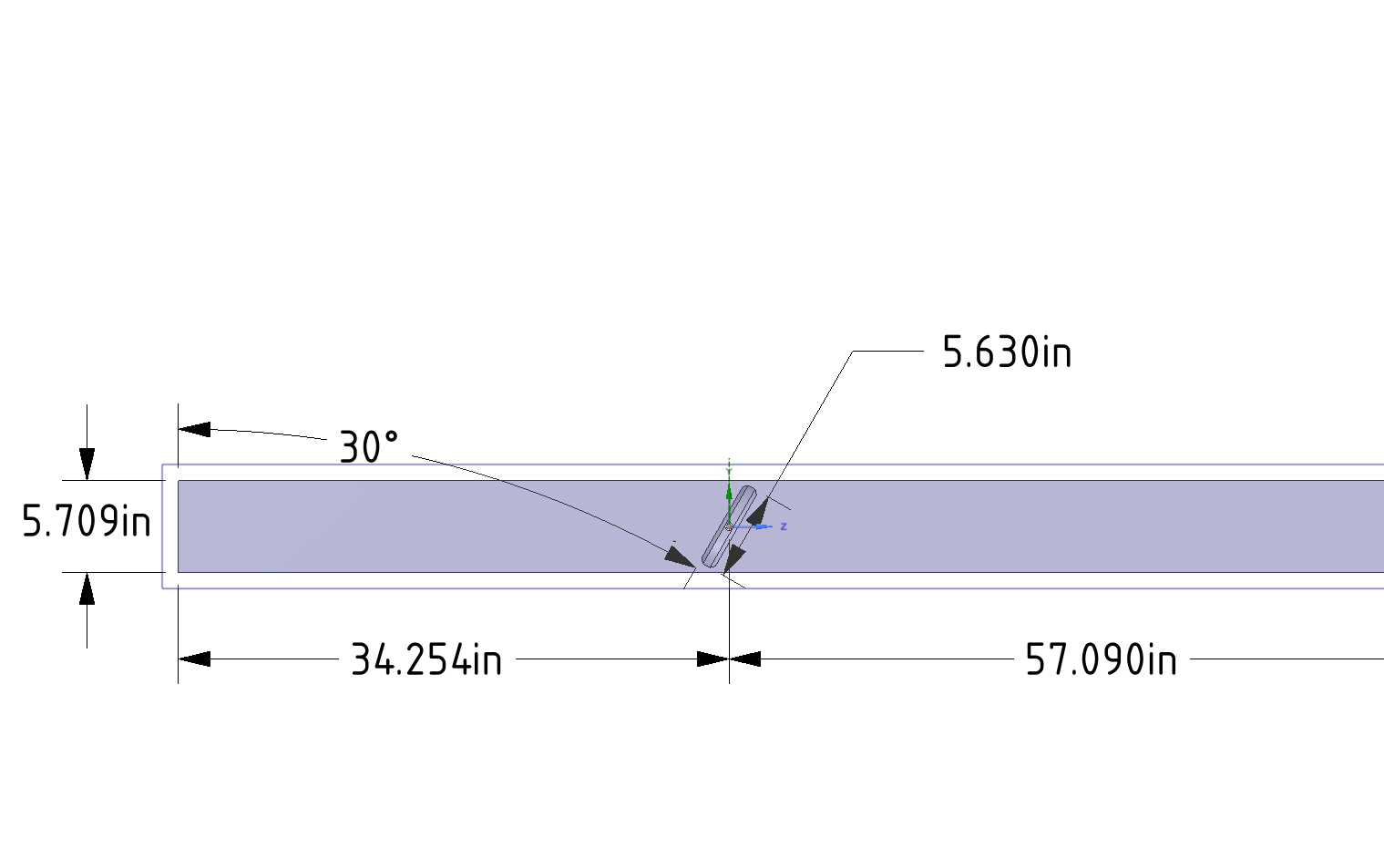
I need some help adjusting the snap settings for my geometry. I am exporting a step file that models a butterfly valve partially open. The section near the axis has a small gap that I need to include in the model. It becomes more important as the valve closes.
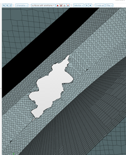
My issue is the Snappy Hex Mesh is “closing” the small gap. I have used surface refinement on the pipe wall, axis surface, and disc surface. Those help but it still wants to “jump” across the gap and close the gap.
I believe my issues is in the SNAP settings. I have played around with them but haven’t figured out how to make this a clean mesh.
I have temporarily closed the gap by decreasing my Base Mesh cell size such that it is much smaller than the gap. This is somewhat annoying because it requires a fine mesh for the entire system, making the simulation more CPU intense. I also changed the snap tolerance and a few other iterations.
Is there a way to adjust the snap controls without having to reduce the base mesh size?
mhm - so from looking at the images, I have not a clear picture of the geometry and the gap you’re talking about. An image of the CAD model + an image of the overall mesh would be great to get an understanding for the overall meshing procedure.
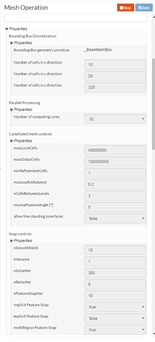
But maybe a general hint can already help: Did you already try/work with region refinements? Region refinement allow you to control background mesh fineness without any reference to the underlying geometry. You can simply define a geometry primitive yourself and then assign a certain refinement level to it. That way you can steer mesh resolution without a surface refinement and/or changing the background mesh fineness. To do so:
Add a “Geometry primitive” to your mesh operation that “covers” the gap / area around it
Add a “Region refinement” and assign the geometry primitive to it
Specify a refinement level for this region refinement
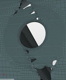
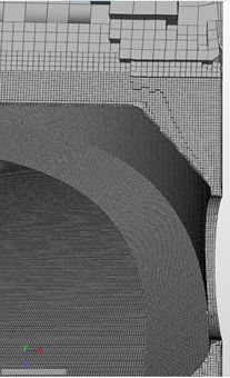
I made a mistake determining what level of refinement was required to model the gap between the disc OD and Pipe ID. I had tried using regions, but the refinement level was not high enough and it couldn’t “snap” to the surface. Surface meshes failed because the “higher level” refinement does not engage until the feature angle is exceeded.
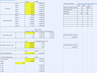
Once I made a cylinder to match the disc and increase refinement to level 6, I generated a great mesh. The picture below is a regional refinement level 6 in the critical area. The spreadsheet below is a nice tool to determine the required coordinates to make the cylinder rotate.