Hi!
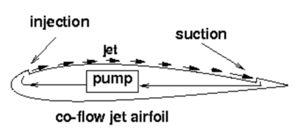
I’m working on a concept similar to this: ((CFJ) Introduction)
In my concept, I’m trying to apply a similar method to propellers. So I’m trying to make a simulation to see how well it works (or not works).
On my first simulation I have the following setup:
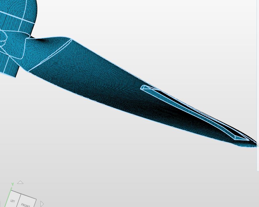
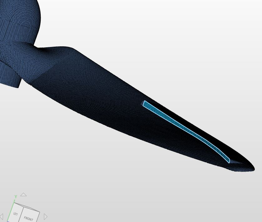
- A propeller in an MRF zone
- An inlet to the upper surface of the propeller blades (it looks similar to the injection part of the airfoil on the picture)
The problem is that the jet doesn’t seem to have any effect whatsoever, compared to when I simulate without the jet. So I’m guessing that you couldn’t apply it in an MRF-zone, in this way. If that is the case, why not?
How could you model this in a better way?
2 Likes
Hi @IngemarJ and thanks for reaching out to us with this fantastic project!
Do you mind sharing your project with us which makes it a bit easier to grasp the concept you are using. Once we can have a look at your model we will get back to you with some input.
All the best!
Jousef
Hi!
I did the simulations one more and more clearly , and public. I also did a test to reverse the flow. I might have misunderstand the function inlett in simscale. There is almost non difference between the different configurations.
Here is the link to the project : SimScale
Hope you can help me,
/ Ingemar
Hi Ingemar,
I think its not showing up because you’ve assigned a no slip boundary layer at the same location as the “blade inlet”. Do observe the screenshots below. The first is the assignment of no slip wall for the prop and the second is the assignment for the inlet and both conditions are applied onto the same surface. Just remove the surface for the inlet at the blade from the wall no slip condition and re-run it, it should show up.
Cheers!
Regards,
Barry
1 Like
Hi Barry! Thanks for the tips!
I changed so the face is not selected for no slip, still there is no noticeable different.
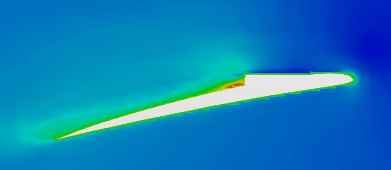
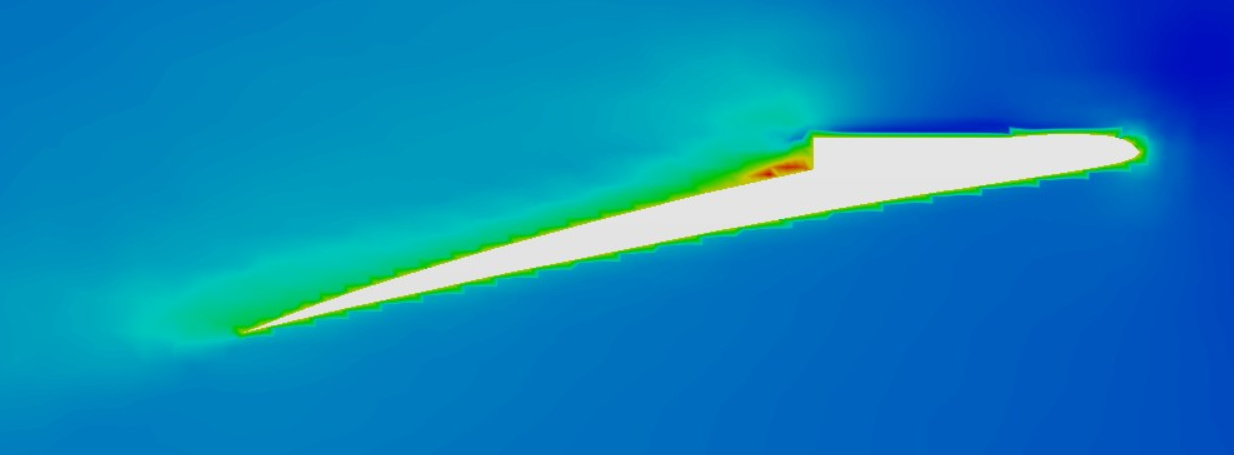
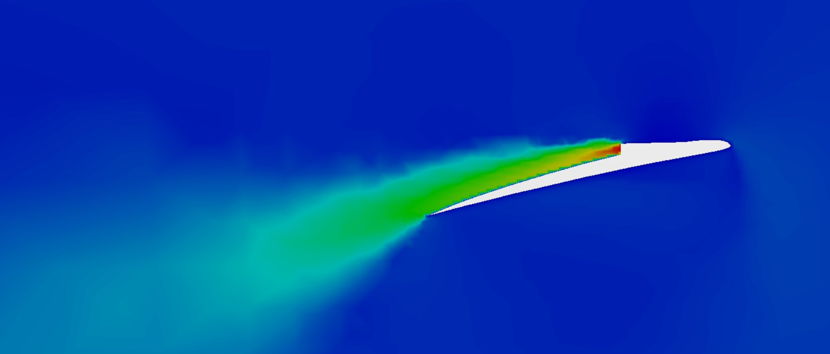
I took one slice picture from each of the three case I study to confirm the inlet effect.
lvl.17.Flow50ms.no.wallslipp
lvl.17.Flow.negative.50ms.no.wallslipp
lvl.17.No.Flow.
The red area with intense speed is a effect of the centrifugal force as I understand it.
Do you have more tips on how I can proceed to make the effect of inlett flow?
Best regards
Ingemar
Hi @IngemarJ,
Its hard to tell from my side but I think there is flow. I will increase the flow rate significantly to see if there it actually is showing up but from my preliminary post-processing it does seem like it is sort of working.
Get back to you soon.
Cheers.
Regards,
Barry
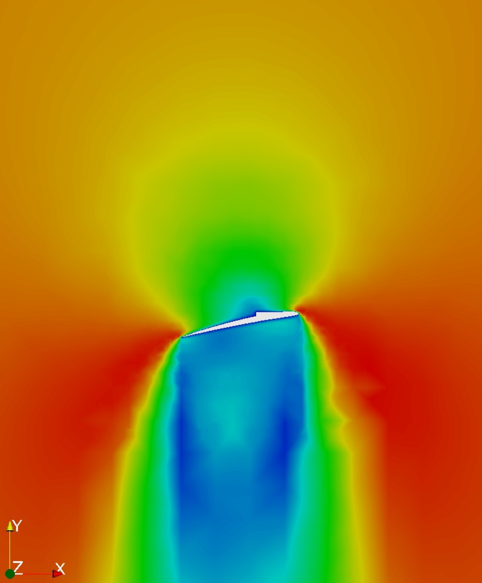
Hi @Get_Barried
I found some issus, or I identified a problem. If I stop the rotation of the rotaion_zone I get this result:
0 rad/s, 50 m/s
And when I set the rotation to 0.1 rad/s the effect from inlet disappears as shown in the picture below:
In this picture all flow is produced from the inlet flow from topp wall (2,36 m/s)
The only difference between these two simulations is that in the first picture there is no rotation and in the second picture there is a low rotation speed at 0.1 m/s
Any ideas of how to combine rotation zone and inlet flow in the rotation zone?
Cheers!
Regards,
Ingemar
Hi @IngemarJ,
I have raised an issue on this, when you download the file and look at the assigned boundary condition for face_20 you can see that it is no longer an inlet.
If there is a work around I’ll let you know.
Best regards,
Darren
Hi Darren and Ingemar,
interesting problem. Does it have to with the assignment of the boundary layer or the internal cell zones?
Sounds good. Cheers Darren!
Regards,
Barry
Hi @Get_Barried, not sure, I think the intension is to change no-slip walls to rotating walls. However, seems to do it for inlets too. This might be intensional and a proper method might be available in advance BC, but ill keep you posted.
Best,
Darren
1 Like