Hello,
I wanted to do a simulation on our FSAE car.
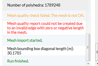
The meshing went well bc I did it like in our FSAE workshop homework.
But I wanted to do the whole body as one part and not differ between wings and so forth yet.
Even though my meshing went well the simulation failed due to numerical instability… I do not find the mistake.
Could someone who has a minute for me look at my project and may help out?
here’s the link:
Thank you for the great support here 
Greets
Hi @estephan,
Is the project private? It doesn’t open when I click the link.
Best,
Anna
Hey @anon18194957,
maybe she set it to private.
Also tagging @pfernandez here. I think there might be an issue with the geometry but I am not quite sure. As an expert in such problems he will probably find the “glitch” very fast 
Cheers,
Jousef
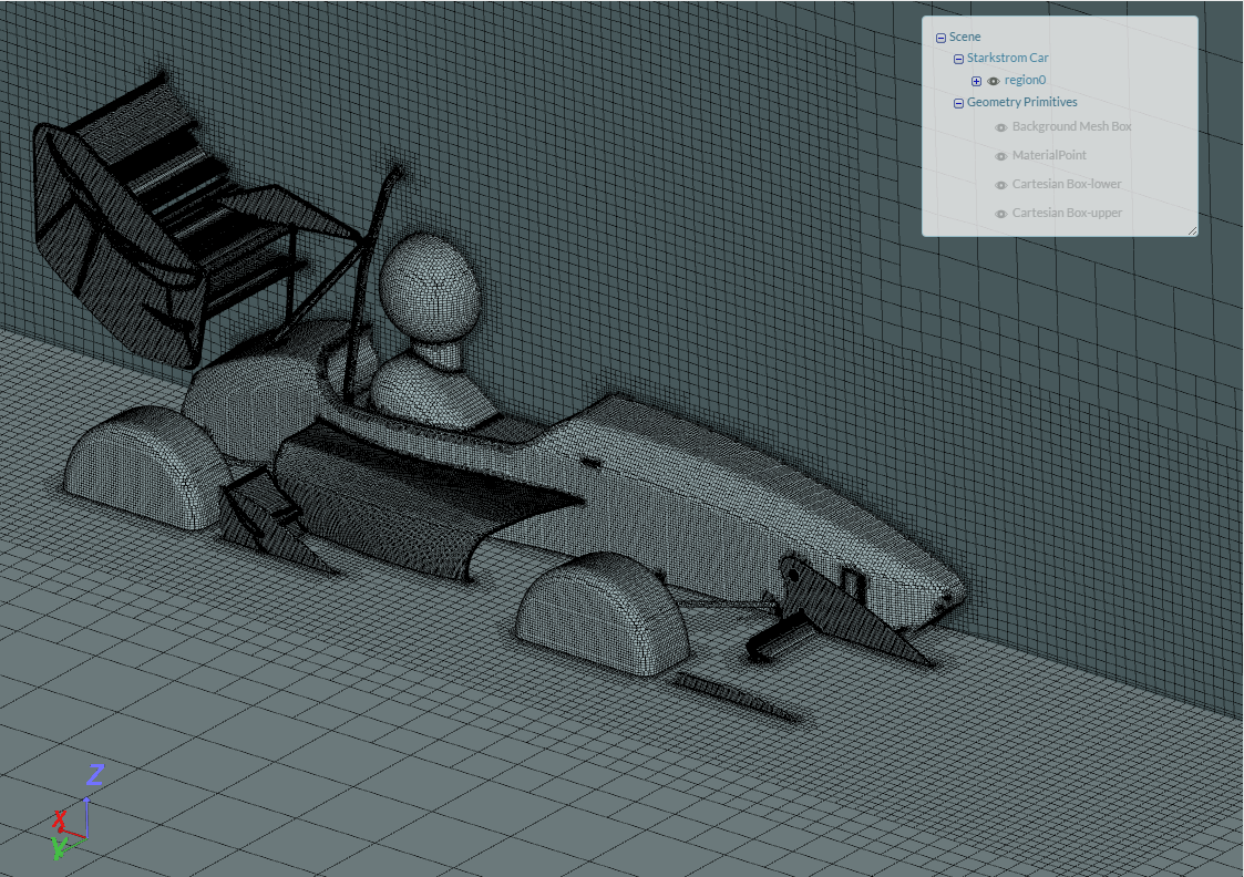
i generated another link. the project was not supposed to be private. I dont know why it didnt work. thanks for the support. I got issues with the geometry starkstrom car which is actually our formula student car for this year.
thanks in advance @anon18194957 thanks to you to for looking at my project.
Ciao Estephan,
on your car I cannot see the boundary layer cells. I saw them only on the floor. It will influence your final results, but I am not sure it is also the cause of your instability.
Cheers,
Fabio
thanks fabio for the reply. I am not sure whether this is the cause but i would like to do the car as a whole first otherwise i will search for a mistake for years if I look at several different parts… I could try to do it with several parts but i dont think thats the issue here. you know a way to do it as one single car as a whole? many thanks.
Ciao Estephan,
I do not understand, what do you mean with several parts. you meant that at the moment you have just one patch for all the car?
Cheers,
Fabio
Several things:
- You have to split the geometry in order for the mesher to be able to generate prism layers in the wall boundaries.
- Get the floor right. Right now, half your car is under the floor level.
- Initial velocity is (0, 0, 0). Consider specifying a constant initial flow even though you are starting the case with a potential flow solution.
If everything else is just like in the workshop, you should be fine.
Cheers,
I meant like I differ between wings main body tires… and not everything as one body 
thank you very much. Why is the car so deep down. It looks like our CAD is not at the origin as the boys told me. I need to fix it 
 I’ll try my best. Do I only have to differ between wings tires (MRF) Porous Zone and main body or shall I have to even separate those right away in single parts like flap, main element and endplates?
Do you know by experience whether you can leave the sideboxes open as they are in reality?
is it enough to put less then 1 m/s for velocity in the initial condition?
thanks alot
Update: @pfernandez thanks alot, it works now! you were right, the simulation wanted different assemblies as input data. Now the simulation runs and the residuals look normal.
[Could be solved! Thanks alot!]
I am looking at another issue: the grounding effect. Therefore I took the same simulation CAD model and placed an offset to the background mesh box so that the car is “flying”. it is the same model as before where it worked. Can someone help me?
btw. how can I make another link. I guess it does not work anymore or I dont find the function.
Project Link: https://www.simscale.com/workbench?publiclink=81a94eca-0df0-4572-8c98-108b67e29153
Thank you in advance