I’m a CFD newb, but I’m hoping to gain a sufficient level of understanding to enhance the function of hobby level part cooling solutions for 3D FDM printing. I’m attempting to generate flow analysis for split ducts that are fed by a single volume flow at relatively low relative pressures, and expel into free air around a few obstacles . I hope that someone might be able to offer some guidance of setting up geometry and initial conditions to get good, comparative results. At the moment I feel like I’m getting no where fast!
I would choose the walls of the duct as a no-slip boundary condition but before doing that also make sure that the velocity inlet (which you already defined) has some added inflation layers which ensures boundary layer creation. For the free air I would just make the domain bigger and define these walls as slip. For any suggestions I will tag my colleagues @Anware and @vgon_alves.
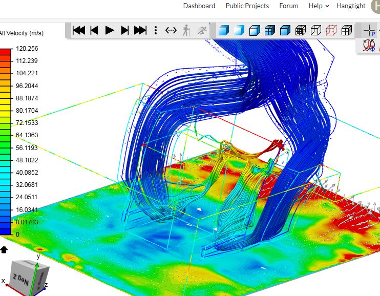
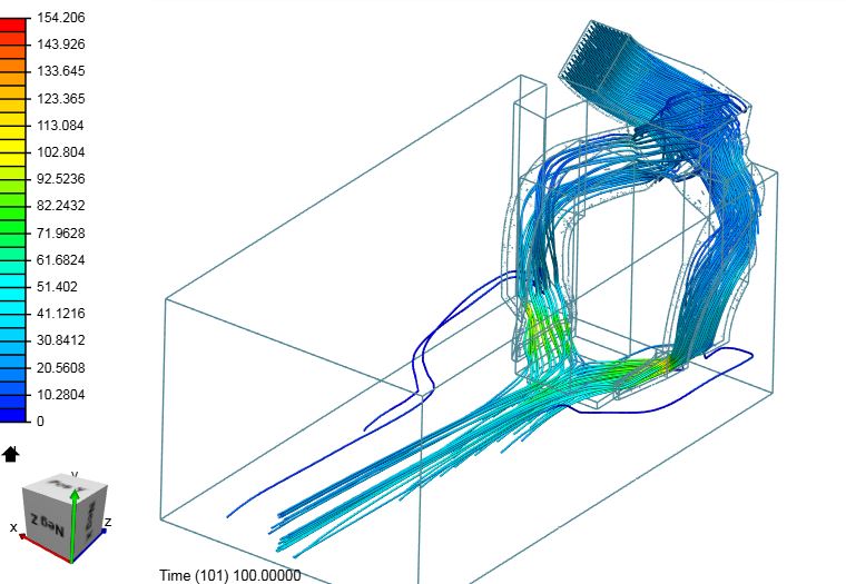
Thanks for the response. So far I’ve been defining a face of the geometry as a velocity inlet, with a volume flow of 90cu.in/min. I’ve also modeled a significant volume of what should be free air at the exit from the duct, defining the sides and top as pressure outlets set at 0Pa and a global pressure of 101325Pa. But I’m getting particle traces that don’t correspond with smoke tests of the actual duct. So I’m obviously setting it up incorrectly, but I’m a bit stumped.
Talking about smoke tests - can you share the data with us if available? The best is always to have direct comparison like turbulence model used etc. (if talking about numerical validation) or experimental setup as in your case to mimic the simulation as good as possible.
The smoke tests are nothing more sophisticated than using a vapour generator so the airstream becomes visible. At the moment tests show a converging flow that generates good velocity across the nozzle tip and exits to the rear, with little spill over onto the heater block
Got it but where exactly (maybe show it in the post-processing screenshot) does it look odd to you? I would still say that the box you modeled for free air is too small. Why don’t you just upload the “manifold” looking geometry and let the mesher create a domain (bounding box) around the object? Would be straightforward and worth a try.
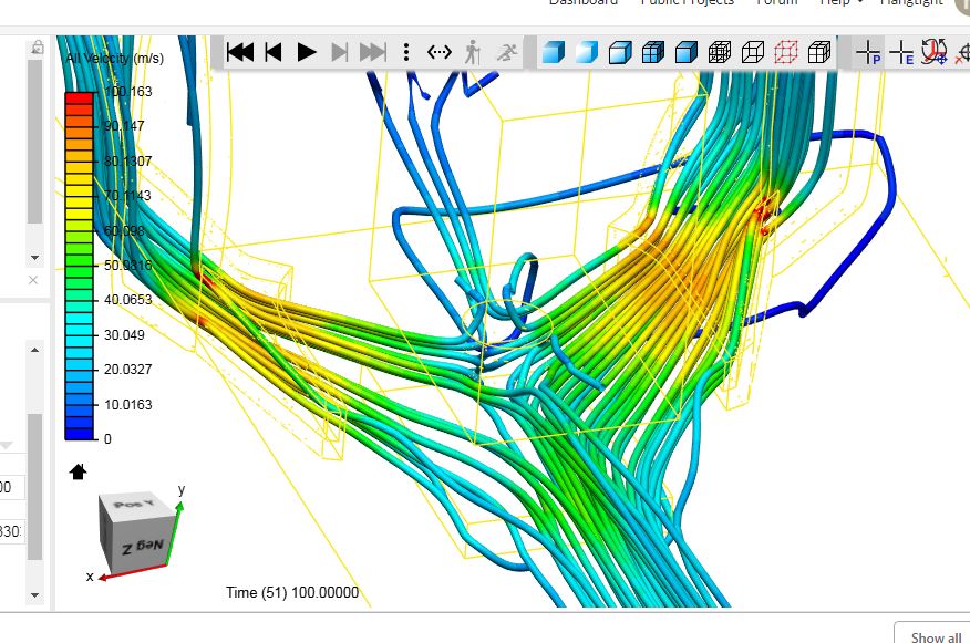
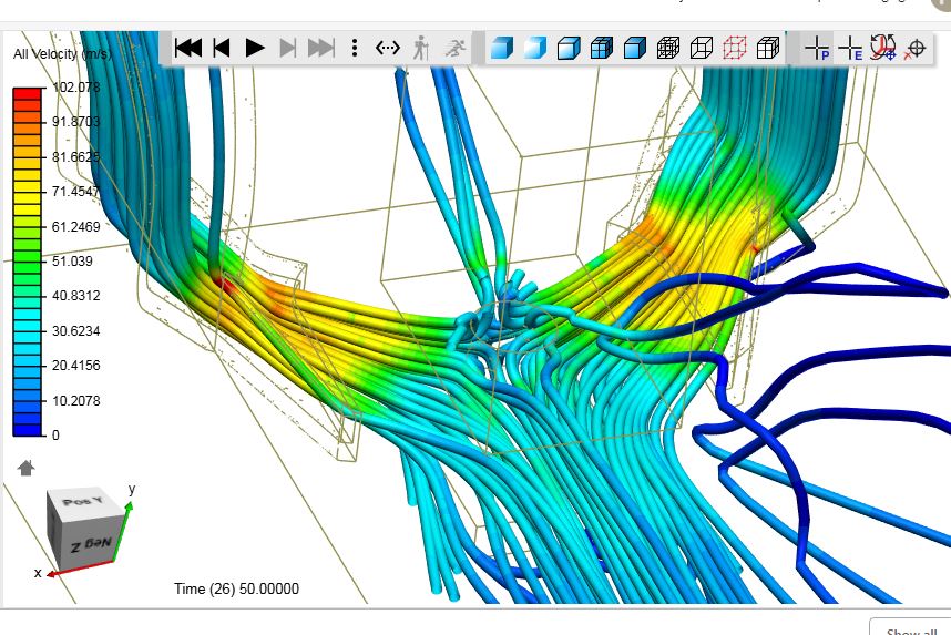
That sounds like a good idea, but I think I lack the knowledge/experience to set that up. on previous occasions when i’ve just loaded the manifold I’m only able to create an internal mesh which gives me an idea of the internal flow, but not of the nature of the flow in free space once the flow leaves the nozzles.
What you can do is to upload the manifold and use a parametric mesh making sure that the material point is not inside of the manifold resulting in an external flow analysis and simply increase the size of the bounding box to make sure the material point is still inside the domain (but as mentioned outside the manifold).