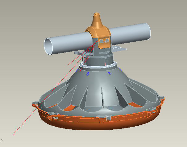
This is a practice exercise for one of my subjects. Currently I want to simulate this setting (automatic chicken feeder). My product frequently breaks at the arrow position. The material is PP (Polypropylene) plastic (the pipe part is steel). I want to simulate the broken position and the direction of improvement? Anyone who has a way to handle this can help me more (where should I put contacts, …)? Thank you
Hi @nmtai , it looks like this is a snap-fit. Does the design break during snapping/assembly or during operation?
Best,
Darren
1 Like
hi @dlynch , My problem has the following notes:
- Feed weight 2kg
- Do not remove often (1-2 times a year)
- Force Caused by people and farm animals.
The main impact is due to the direction along the pipe because when the horizontal impact, the chute has already rotated
So is such information enough to conclude the general cause? Or do you need any more information?
Hi @nmtai, ok, I think I understand. So I would say that your simulation is likely to be needing the following:
- A static simulation (structural module)
- You should create a simple geometry, removing parts (and features) that do not significantly influence the breakage. The more complex the geometry, the higher the chance of having mesh-related issues, expenses, and time delays.
- Apply a representative force in the direction you describe.
- Use stresses to determine if the product yields. If it doesn’t, the breakage could be caused by fatigue, in which case the highest stress points indicate where a breakage occurs. Ideally/likely, the breakage you have experienced will be at the highest stress concentration.
- Use the results, and an iterative design process to improve the part and reduce the stress.
The tutorial for structural simulations should give you a good starting point.
I hope that helps!
Darren
Hi @dlynch . I have an idea . Instead of applying an axial force (which causes displacement of the part attached to it) I will set the other part to default to displacement a distance while it considers the behavior of the model. So according to experts, is this approach suitable, because I don’t know where the force is located. Thank you
That approach would also be fine. Just try with a small displacement first, and make sure you let the displacement rotate and move in the other axis ( don’t over-constrain).
Thank you very much . In your opinion, how much displacement is okay. And why this post is Static Linear and not Fatigue Analysis.
No worries, it depends on the scale of the part. With the scale in my head, I probably start with no larger than 1-10mm of displacement, observe the results, and make sure they make sense. Before increasing the simulation complexity, you must observe the results and ensure they are sensible. Start simple, and take it a step at a time ![]()
Fatigue is usually a post-processing step on top of another solver, so depending on your experience, they may be the same. I’ll be completely transparent here: SimScale cannot output fatigue-related results such as the number of cycles. However, max stress will most likely be enough to tell you where to concentrate your design improvements and how to assess an improvement.
Best,
Darren
@dlynch .Thank you very much.