Hi,
I am running as test a simple duct with single inlet and multiple outlets.
I set BC such us inlet velocity and fixed outlet pressure = 0. Incompressible k-e model.
link: https://www.simscale.com/workbench?publiclink=4233bb4e-5ac5-47d4-82c7-76464c86fa9b
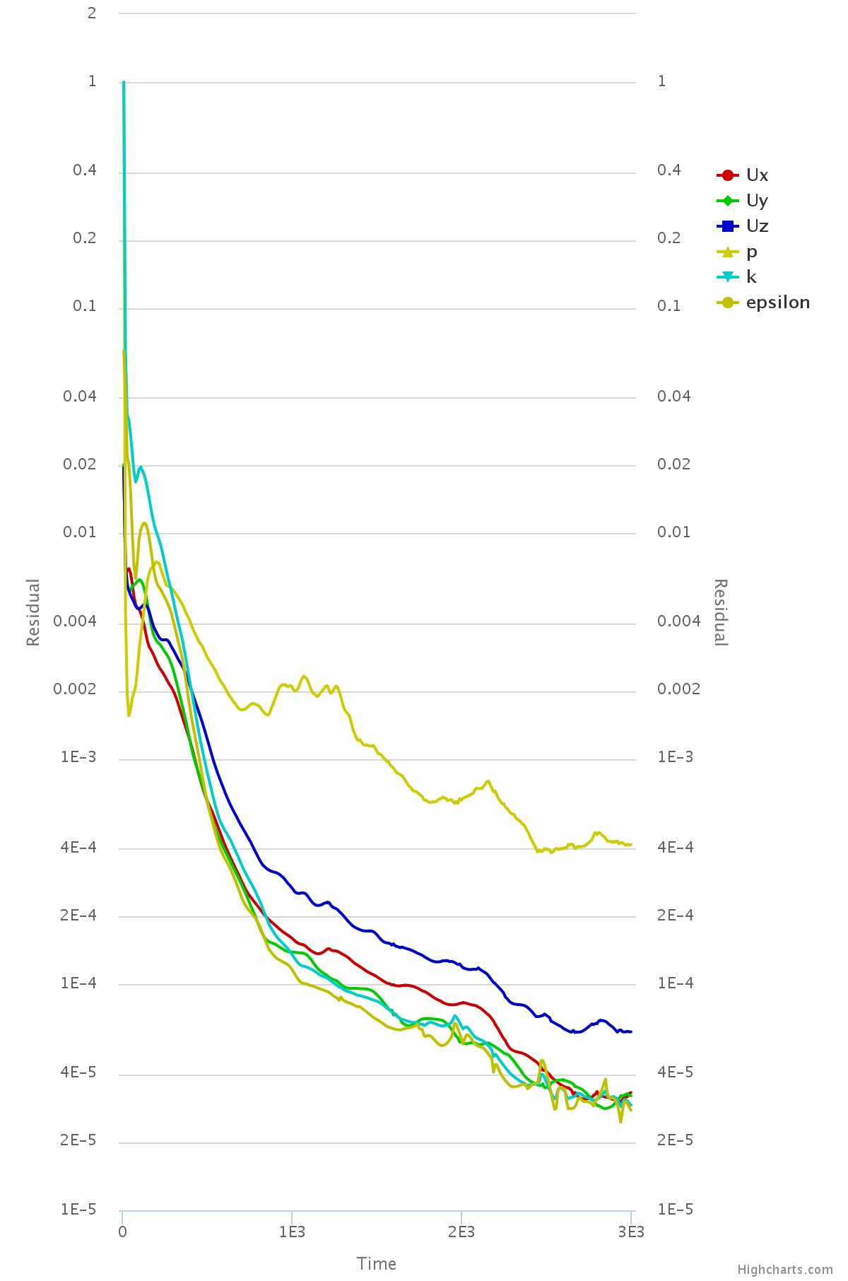
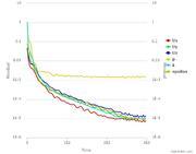
Convergence plot seems ok, meshing log OK (no Bl for now), but results shows that velocity jumps
to non physical values (like 2 orders of magnitude higher thatn the inlet condition of 14m/s)
I am a little bit lost in which is going wrong, if BC, mesh, geometry?
please any help welcomed.
Regards
Hi @rulmismo,
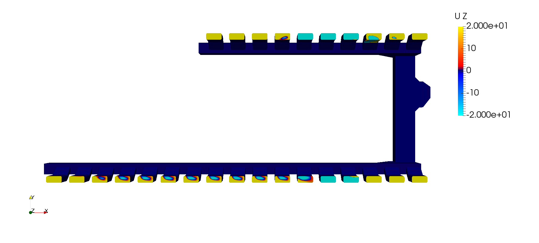
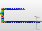
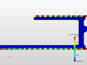
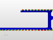
I detected some backflow in several of your pressure outlets. See the images where I coloured by the z-component of the velocity:
Also, even though the residuals did not diverge, that’s not the trend I would like to see in a good simulation. Have you tried to impose a Total Pressure boundary condition at the inlet?
I’ll run some test myself and see if I can find a solution.
Regards
1 Like
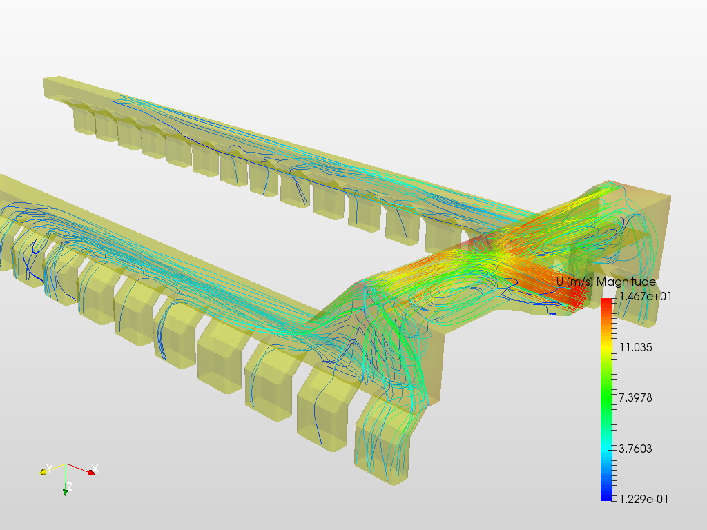
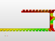
I managed to improve the simulation results just by adding boundary layers to the walls.
With that, the convergence has improved significantly and now the velocity stays within the same order of magnitude.
You might want to increase the number of iterations in order to achieve better convergence of results.
5 Likes
Hi,
thanks for the reply. I did the change to mesh with BL and now, as you already have verified, the results seems something sensible.
Some questions regarding the topic and your data:
1- I have had some experiences with difficult geometries in which is very difficult to pass the mesh quality checks if BL mesh is included. These “bad-cells” gave me some blowup numerical comvergence problems.
I also read somewhere that in flows where the pressure drop is caused fundametally by geometrical constraints or “obstacles”, the frictional component added by the walls was of lower importance, so I assumed it was of less importance to assure the y+ value near the wall, and use the BL mesh. So that´s why I did not use it in the first place.
Obviously I was wrong in this case, and for this case not using the layer mesh causes to get a “solution” where it seems two outlets are somewhat “shortcircuited” with a non physical ridicolous high flow.
Any comment/opinion on the previous is welcomed,
2- on respect to use a pressure inlet condition, Do you propose use two pressures as BCs? Usually for ventilation systems a flow is required, so it is the natural condition to start with. Once the pressure drop known, the fan or blower is selected to match it. It could be used also the custom "fancurve"custom BC, but not sure how.
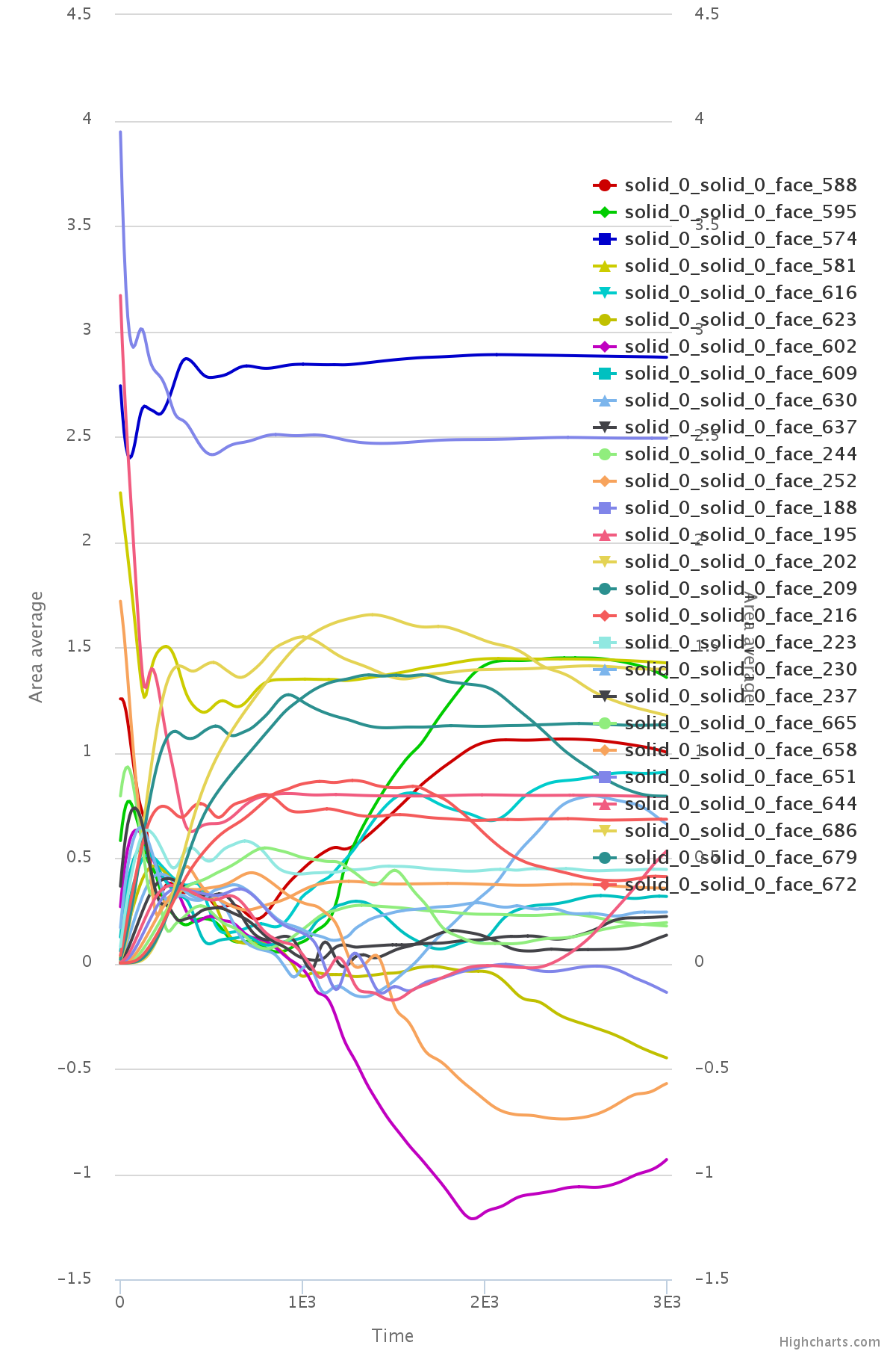
3- what is exactly the last convergence graph shown and how have you got it?
thanks and regards
Pressure and velocity are linearly coupled in the discretised form of the Navier-Stokes system; so you should be able to impose either a pressure difference between inlet and outlet of a velocity at the inlet and a pressure at the outlet. But that will depend on the knowns and unknowns you have.
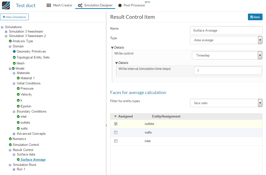
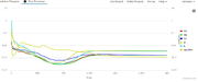
The last graph is a surface area average: Result Control > Surface data > Area average.
1 Like
Hi, thanks for the reply.
I tried to get into a more complex BC such as “fanpressure” in order to simulate a flow restriction in the outlets.
For that, following a forum example I used flow direction “out” and a negative flow vs pressure curve.
The simulation seems to proceed well althought pressure residual remains a little high. First doubt is if that pressure residual can be considered ok or not.
Comparing the results of both cases (initial case with free outlets vs case with “restricted” outlets) I would expect to have a similar results in speed distribution and pressure in the duct, with just order of values changing.
The expected outcome is as the result of first case, (free outlet), with a over pressure where the main flow is forced to change direction due to geometry. I.e. at the inlet T junction, near the first outlets (due to the geometry bend) and near the end of the duct.
However in the “restricted” outlets BC case, the pressure shows a similar pattern (over pressure in first and last outlets).
BUT I get a somehow fancy result in the speed distribution, with more speed in the mid outlets
any comment welcomed
Project: