Hello,
I’m trying to simulate a case where a ship hull has ducts to communicate front water from the bow region to the propeller at the stern to reduce wave-making drag. In this scenario there are 2 flows affecting the hull, external (the ambient water) and, internal (the suction of the water by the propeller) any advice about the setup will be appreciated.
[The ship hull geometry]
(https://www.simscale.com/workbench/?pid=1275230874393042108&mi=geometry%3A6&mt=GEOMETRY)
Hani
CFD Squad, can you have a look at our user’s project please? 
Best,
Jousef
Hi Jousef,
I did not find any project that is similar to mine. Did you get the chance to look at my concept geometry?
BR,
Hani
Hey @haniyousef welcome to the forum!
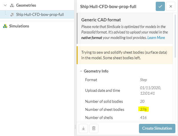
Unfortunately you will have some work to do on your CAD model as Simscale does not play well with sheet bodies. Your geometry seems to have quite a few of them. For a successful mesh you must remove EVERY sheet body. To do this you have to have solid bodies (volumes) for your parts. Until this is completed i would not try to mesh anything as you will most likely just receive errors.
Good Luck! Looks like an interesting design!
Dan
Dan,
Thank you for taking the time to have a look, I’ll surely resolve the geometry issue asap, but I was wondering if you were able to understand my concern regarding the settings for this case. Is the concept clear to you?
BR
Hani
Ah yes i forgot about that part.
So a couple of things first to improve your geometry.
- In simulation, anything that does not impact result performance should be removed, mainly small features, so your attachment hinges should be deleted.
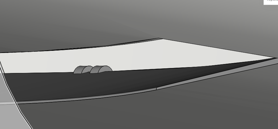
This flap should then be tight to the hull. although im not sure what the purpose of this flap is, as i would think this in itself would cause massive amounts of drag
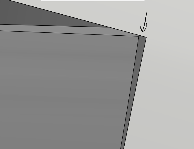
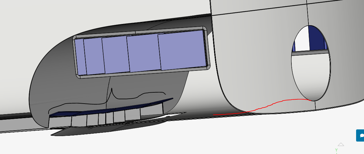
For this flap … same thing, remove the hinges. Also the geometry should not have any tersections (top arrow) or
Gaps. The small face poking out (middle arrow) should also be removed. This small face isnt detrimental to the mesh it is just better to fix things like this so your not searching for a potential error later.
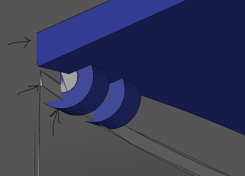
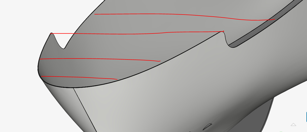
For the overall concept other then the flap jetting out into the water under the hull it looks good! The upper blue flap doesnt seem to serve a purpose as the water will come out between the vertical slats. you can probably just delete this whole thing. Also, at the stern where i assume your propeller hole is, the hole is above the bottom of the hull and there will be water just sitting in this area. Maybe lower hole or step up the rear of the boat to match the propeller height (in red)
For modeling the propeller you can also do one of two things.
- add the propeller geometry with a rotating wall condition . Then add a MRF zone
or
- The Simpler method that will use less resources - create a momentum source where the propeller should be.
Is this what you meant with concept?
Dan
EDIT
I forgot to mention. To reduce mesh requirements its better to just close the hull completely on the top. Otherwise you are meshing the outside and inside walls, which will just waste core hours.
Dan,
Many thanks for your scrutiny of the geometry, you raised very valuable points.
As for the functionality of the concept, it is about feeding the water to the propeller from specific locations around the hull rather than being solely from the stern area. by doing so, the resistance at the bow will be reduced, the friction drag will be minimized and, the ship will have maneuvering capabilities that are not possible with the rudder based steering (BTW, this concept does not use a rudder).
If you are interested have a look at the illustration doc on this link:
let me know your thoughts about it.
I’ll work on the geometry and hopefully resolve its issues soon.
Thanks and regards,
Hani
WOW thats a really interesting concept.
on the second slide 5A is a similar concept to racecar mulit element wings where the slot gap between elements is used to energize/reset the boundary layer.
maybe for a performance increase you could test the transverse slot at different distances from the stern and try to locate it at the best position where the boundary layer starts to become turbulent.
at higher speeds the BL transition point would move rearward so it would be interesting to design this with multiple transverse slots that open/close base on the anticipated laminar to turbulent transition point.
I hope you can get this meshed uisng full resolution. Your going to have some work to do to get your Y+ values down.
Good luck!
Dan
I’m happy to see your impression and notes, so you see that I have 2 flows, one is external, as is the case with any conventional hull. The other is internal through the ducts, from the bow to the propeller chamber and, from the chamber side windows going in towards the propeller. Both of these flows affect each other. This is basically what I’m trying to simulate here.
Hani
Also, a very important point to keep n mind is that the movement of the water in the internal flow is driven by the propeller and not the movement of the hull through the water.
ah yes thats true. make sure to post your solutions field results here. its going to be interesting the pressure difference this achieves.
i also assume you will test this with the propeller chamber side openings closed on one side to simulate a turn. The forces and moment results would also be interesting. Any plans to test turning capabilities based on center of gravity Postion? I would think the vertical pressure retention plate angle would have an effect on performance.
My goal is to do all these simulations, and as you said, it is going to be interesting to see how things will evolve. I’m still in square 1, how can I have the case be configured to take both flows in consideration. Just as an example, when the propeller is turning it will create a low pressure zone in the chamber, this will draw the water from the bow through the ducts. And here comes the interesting part, the simulation is expected to show the effect of this suction at the bow as a drop in the pressure of the external flow. I wonder if I was able to clarify the issue that is unclear to me (2 flows, one simulation)
my understanding is that you can either have:
- an inlet velocty for the water (simulating that the boat is moving) and a momentum source for the propeller with a velocity that is higher then the inlet (applying a thrust)
OR
- no velocity inlet in the domain (boat standing still) and use the momentum source to see the pressure difference it will create
Were you implying/thinking of having two different flows (as you said) with one internal and one external and the resultant interaction in the chamber? If so i dont think you could simulate the bow pressure drop that would result from the propeller sucking the water through.
According to my novice understanding, the external flow will be setup as a flow domain (a cube for example) which will have a velocity inlet with a velocity of, say 15 knots to resemble a cursing ship. At the same time the propeller opening will be configured as velocity outlet with a velocity resembling that of a propeller of a ship moving at 15knots, the openings at the bow, the side windows, and the bottom slot will be pressure inlets.
What you referred to as flaps, are just walls to deflect the water when they are open.
Does this make any sense to you?
Simply said, the external flow is a big domain with its own inlet and outlet configs, and this is the same for the internal flow.
Yes it does make sense but I dont think some the assignments will work. I too have a fairly novice understanding of correct domain setup as i just simulate external aerodynamics so my settings are always the same, i havent dabbled in anything else yet.
This is most defintely correct, one velocity inlet and one pressure outlet on the other side. However, i dont think assigning the Propeller as a velocity outlet will work/is the best way to do this. A Momentum source is better (search in simscale documentation for this).
this is where my knowledge on this topic is exhausted but i think these areas will show pressure gradients by themselves due to the veloctiy inlet / water moving though the hull / thrust forces.
This is where the more experienced power users will be able to help you. I hope they join in.
Yes correct and from what i understand the angle of the chamber slats / transverse flap will allow more or less water to flow and when (for example) one side is closed the pressure difference will aid in turning.
I think you have a clear understanding of the major idea here. I’ll work on the geometry and hope that some experienced users join this discussion.
If you happen to know any of them, would you tag them?
BR Dan