I’m working on a simulation and i finally got all of my contacts and such set and i set a pin connection for one end of a shaft that is going to be in a bearing. The whole simulation depends on rotational motion from the applied force. But when i try to run my simulation, i get an error saying that there is more than one direction of rotation for the pin connection. I’ve tried picking different faces inside the bearing and keep getting the same error. Can anybody help?
Hi @elijahlee,
Thanks for posting your question!
Bearing motion between two bearing houses cannot be deployed using Pin Connection. In this case it is more useful if you apply Physical Contacts associated to a Rotating Motion BC. But first and foremost, it is important to see which geometry conditions are imposed for your particular case. Could you please share the project link here?
best,
It’s not between the bearing houses, it’s between the shaft and the different parts of the bearing that I’ve tried.
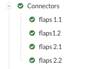
Hello, I am also getting similar error. the error is “There is more than one possible direction for the rotation axis of the entities (A1_I18_B12_TE127) assigned to flaps 1.1. This happens e.g. when the assigned surface(s) define a sphere. Please make sure that the assigned surface(s) define a cylinder.”. I tried for different surfaces but ıt didnt work. Can you help me also?
Hi,
For both of you, could you please share the project link here?
best,
sorry sir but Have you received the link of my project? I just wanted to check if everything is ok. kind regards.
Not yet. But no worries, you can just copy and paste the URL link here in this topic.
https://www.simscale.com/workbench/?pid=7534592283948018555&mi=spec%3A10d892cc-be9e-40aa-8c0c-7fbc4e272451%2Cservice%3ASIMULATION%2Cstrategy%3A2 ıs it okey like this?
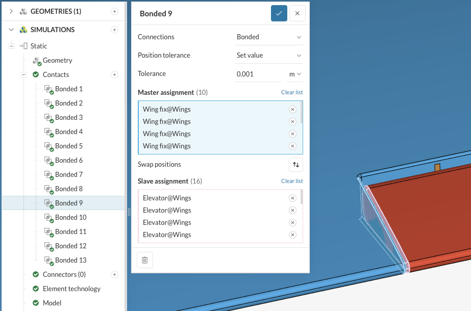
The connectors are causing the issue, so just try to delete them and create a new run.
This definition is just available for assigning cylindrical surfaces to define a virtual pin about which the bodies can freely rotate.
best,
Yes, I know it is caused by connectors, but don’t I need to use connectors for moving objects? The flaps on the wing move up and down, so I thought my description of the connectors would be correct. Can I get a good result if I do not define connectors in my static simulation? Because I will manufacture the vtol I designed after the simulations. best,
Unfortunately for now it is just possible for cylindrical surfaces, which is not your case. Changing these contacts from Bonded to Sliding should be enough (but be aware that adding an artificial elastic support to this volume must be required).
best,
EDIT1: To be clear → Sliding contact just for the surfaces of the volume that you want to allow the movement (not all contacts).