Recording
Aerospace Workshop feat. EUROAVIA (Session 2) ― Bending of an Airfoil Frame
The base model used in this homework session is provided by Aled J Taylor from GrabCAD.
Exercise
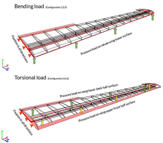
This project involves simulating the aircraft wing with applied bending and torsional load due to wind pressure. The task is quite interesting, to setup 6 different configurations with 3 different models and then compare the results. There is one initial model and two optimized ones. The interesting thing would be to see how the deformation and stresses change with each structural optimization of a wing. The possible load configurations with the initial model is shown below.
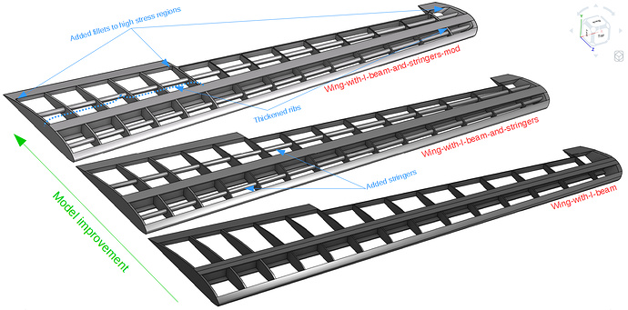
The structural improvements done to the wing model are shown in the figure below:
The different combinations for performing the simulations are:
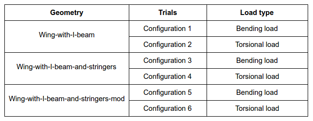
Please, note that separate simulation needs to be set up for each configuration
Step-by-Step
Import the project by clicking the link below. (Ctrl + Click to open in a new tab)
For the sake of simplicity, this step-by-step will cover the first 2 configurations and it can be adapted for the other 4 configurations.
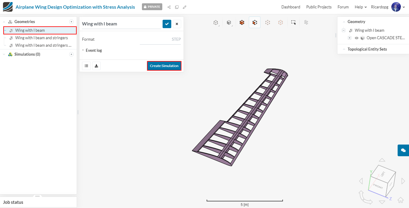
The first step is to select the Wing with I beam geometry and click on Create Simulation:
A window with different options of simulation analysis will pop up. Choose Static and click once again on Create Simulation.
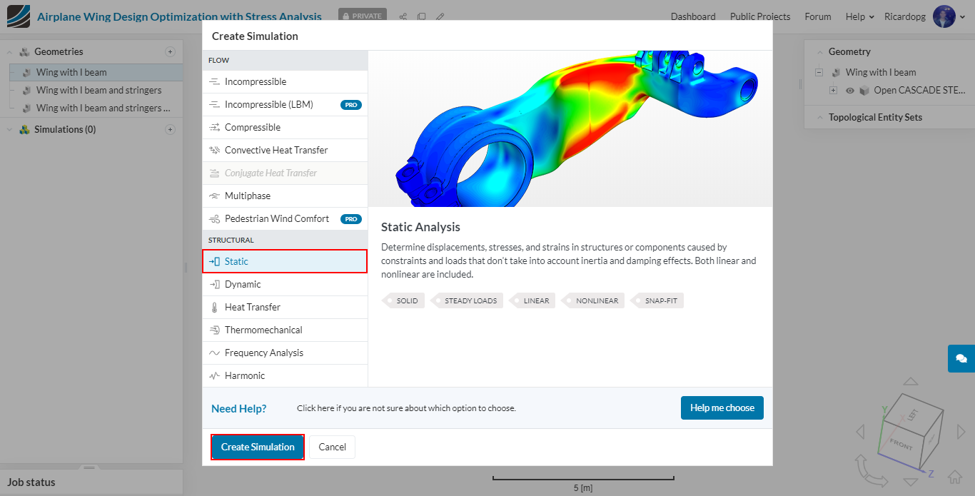
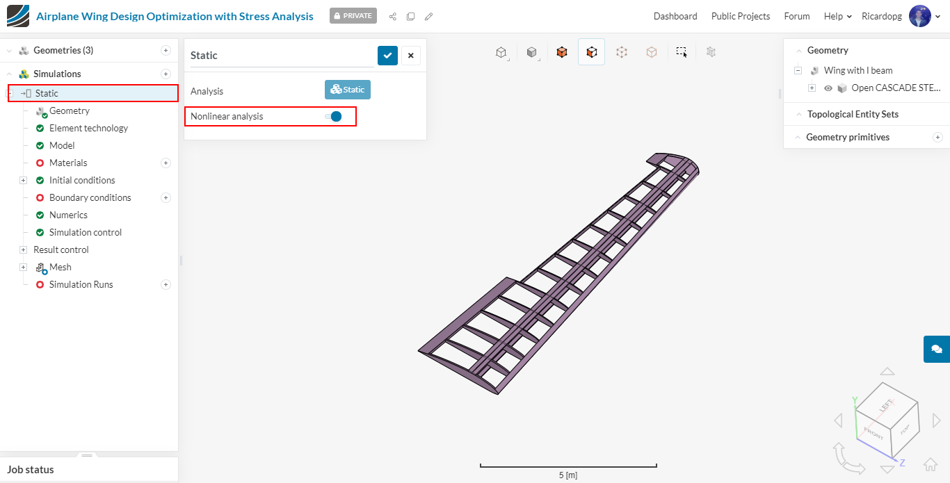
For this project, we are going to use Non linear analysis toggled ON:
Meshing
In the left-hand side panel (called simulation tree), please navigate to Mesh. Change the Algorithm to Tet-dominant. Furthermore, change Fineness to Moderate and set the Order of the elements to Second.
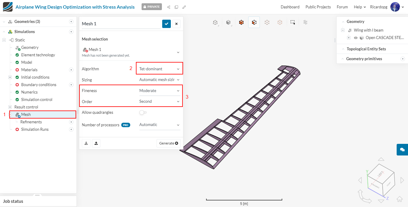
The number of processors is automatically chosen by the software in order to optimize the usage of core hours. Therefore, you can click on Generate to start the meshing operation. The operation takes less than 5 minutes to complete.
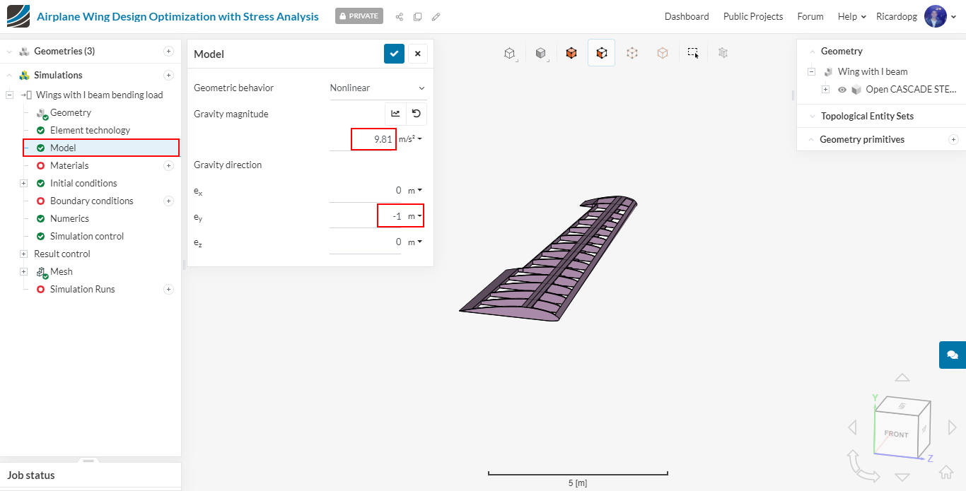
We have to specify the magnitude and direction of gravity. To do that, navigate to Model. Input 9.81 m/s² as magnitude and -1 in the y direction.
Creating topological entity sets
In this project we are going to perform 2 different simulations with each model, as discussed earlier. The image below shows settings for bending and torsional load condition. It is convenient to name these under Topological Entity Sets to be used later during the setup.
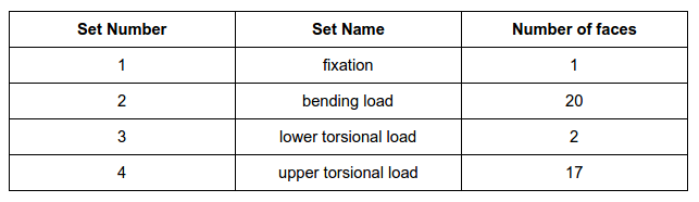
We will create 4 sets of faces in total, as shown below:
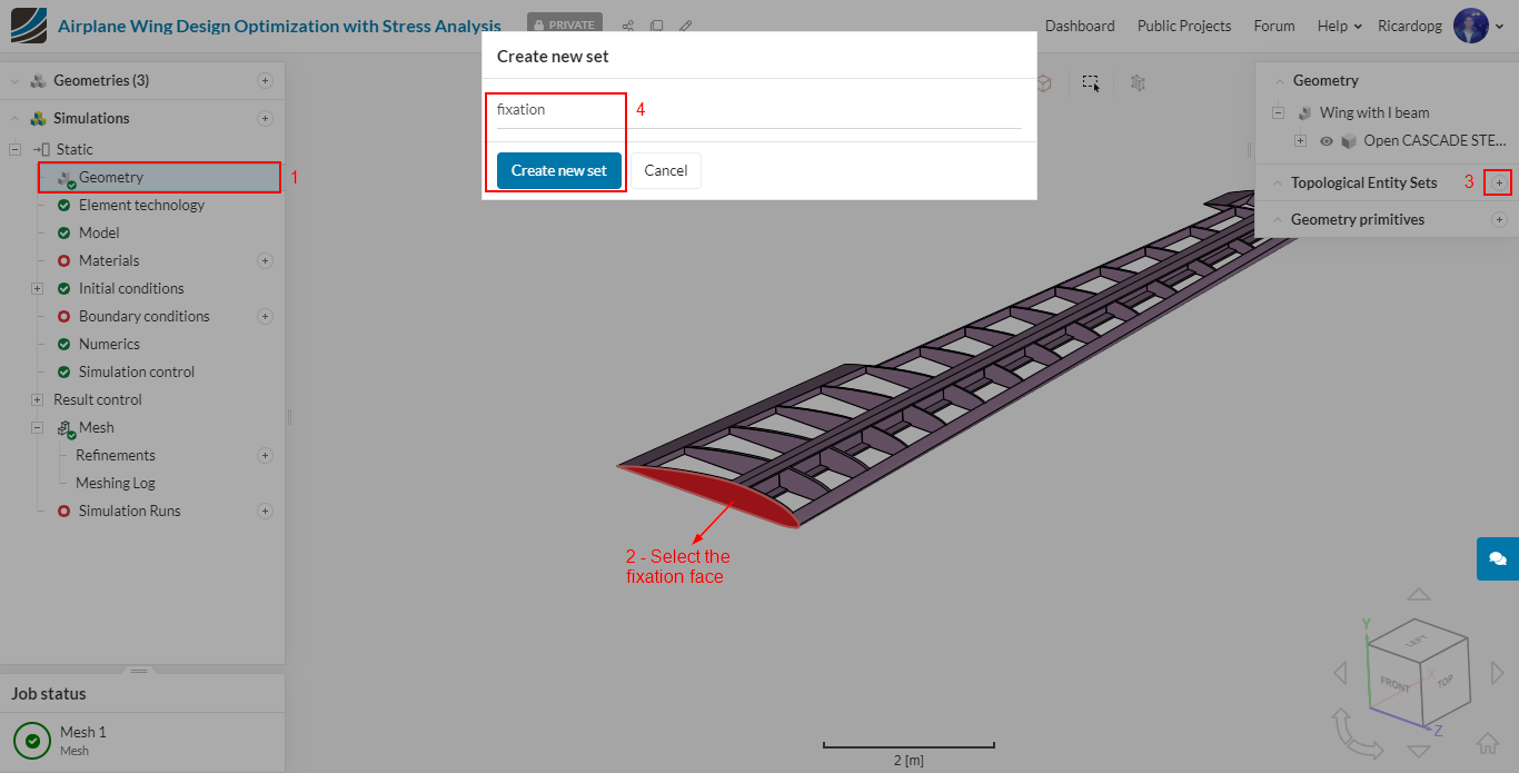
To create a new Topological Entity Set, go through the following steps:
- In the simulation tree, make sure Geometry is selected;
- Select the face or faces that will constitute a new topological entity set;
- In the right-hand side of the viewer, click on the + icon next to Topological Entity Sets;
- Rename the newly created entity set appropriately.
To create the fixation entity set, select the following face:
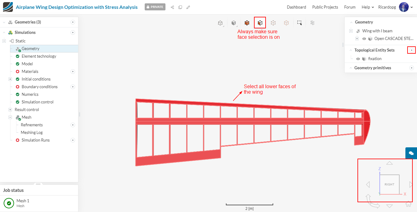
To create the bending load entity set, flip the model upside down and select all shown faces (all lower faces of the wing). You can change the render mode to surfaces to make the selection easier. A total of 20 faces should be selected.
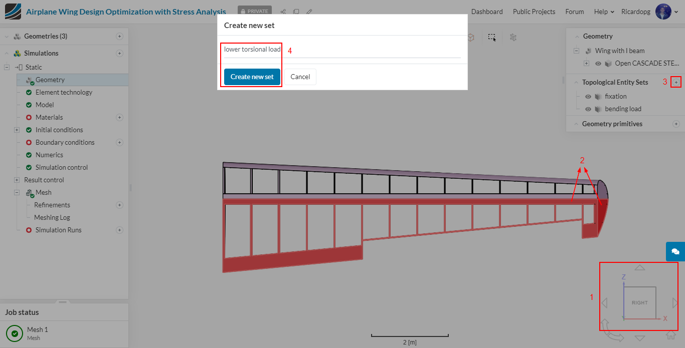
To create the lower torsional load, the exact same model orientation will be used. But this time, select all lower back half faces of the wing. Only 2 faces will be selected for this set.
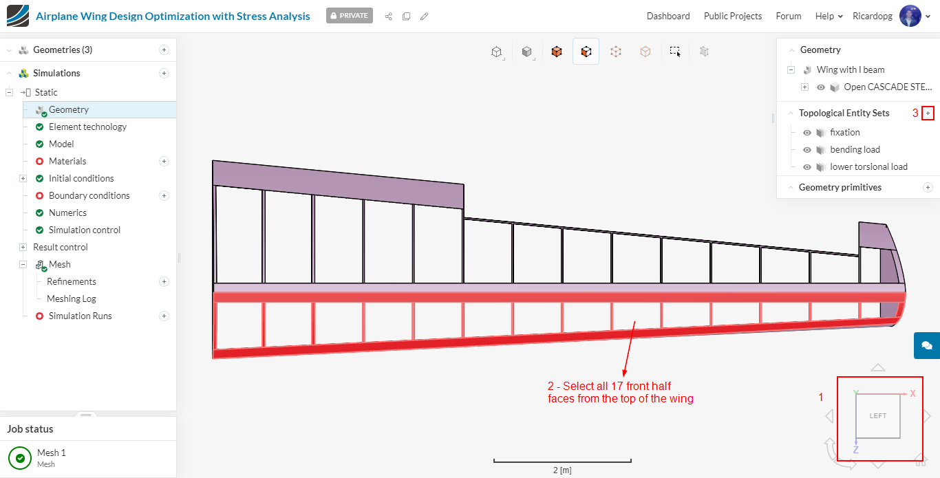
The last set is called upper torsional load. Flip the model and select the 17 front half faces from the top of the wing.
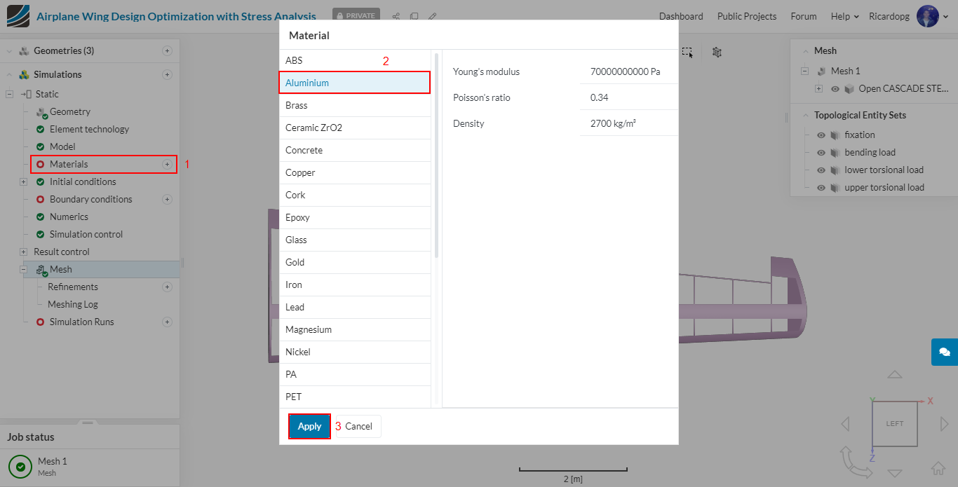
It’s time to assign materials to the wing. Normally different Aluminum alloys are used for specific sections i.e. ribs, stringers etc. But for simplicity we will assign Al 2024 to the whole wing. Select Materials from the sub-tree and click on Aluminum and Apply.
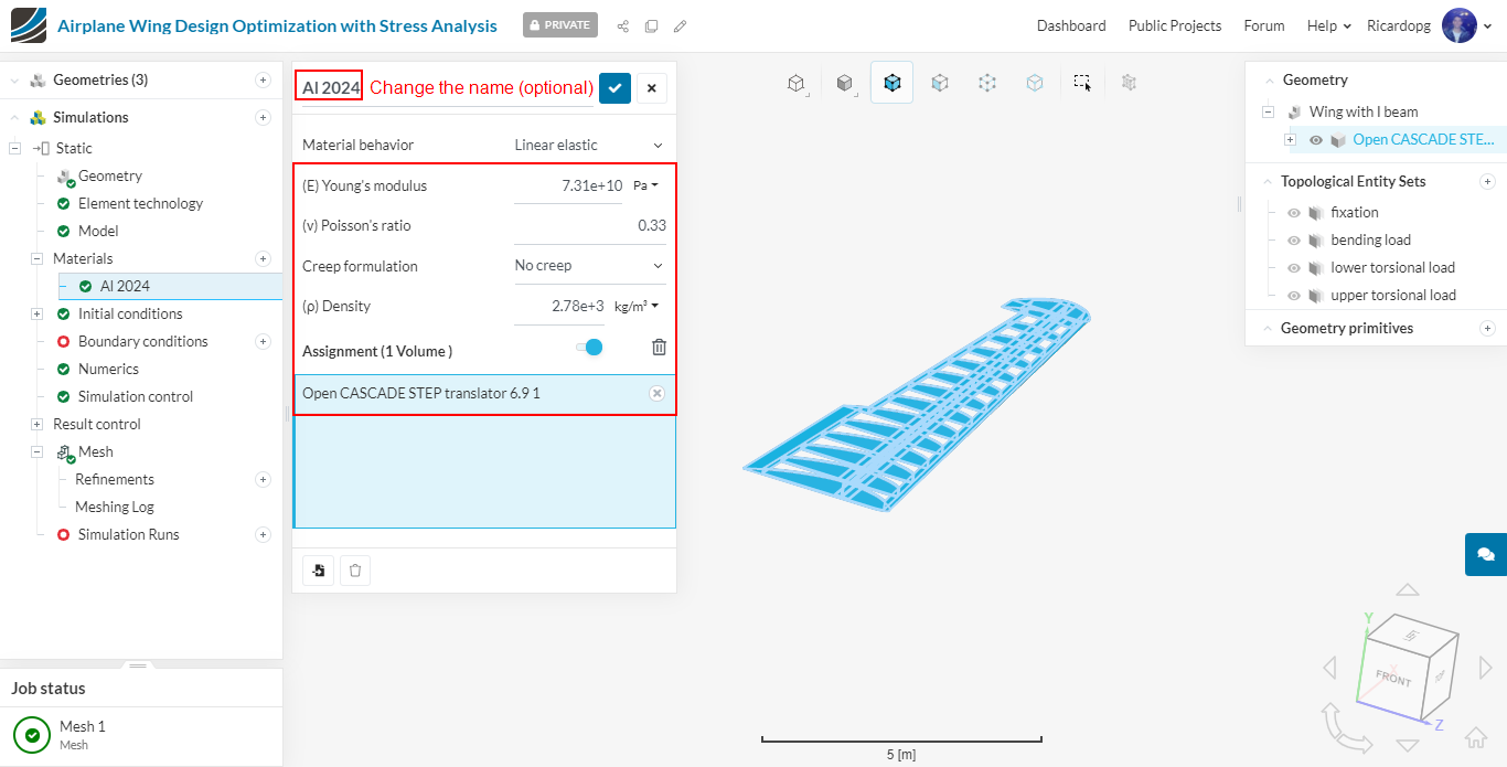
Al 2024 propeties are slightly different from those in the materials library. Therefore, change the properties to these below:
- Young’s Modulus [N/m2] to 73100000000 (defines the stiffness of the material);
- Poisson’s ratio to 0.33 (defines the relationship between deformation of a material along perpendicular axis);
- Density [kg/m3] to 2780 (defines the self load of the geometry).
Boundary conditions
In this section, we will define boundary conditions for our simulation case. The previously created topological entity sets will be useful to assign faces.
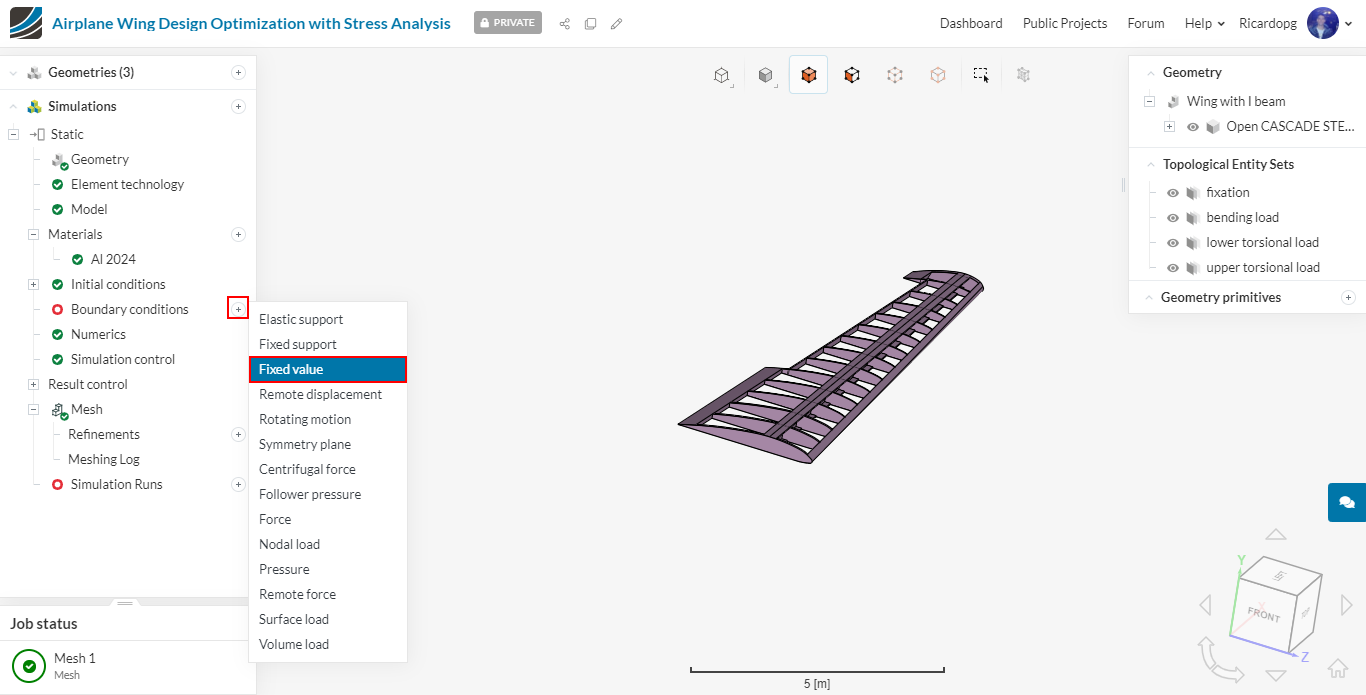
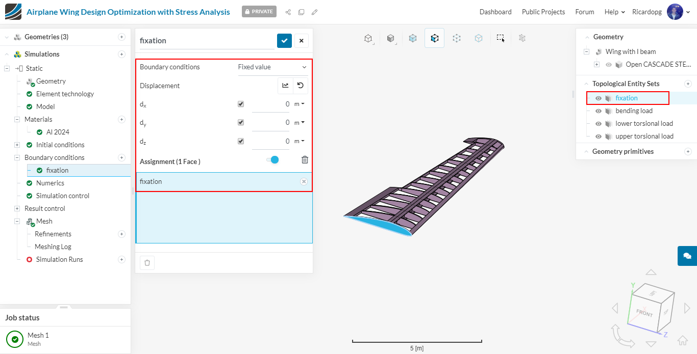
Let’s first define a boundary condition for the fixation entity set. In the simulation tree, select Boundary conditions. Then, click on Fixed value.
Keep Displacement equal to zero in all directions and assign it to the fixation entity set:
Add another boundary condition. This time, a Pressure BC. Click on the arrow to open up more options for the pressure input:
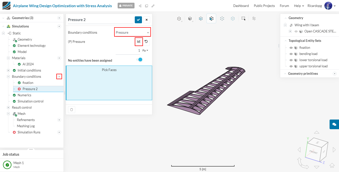
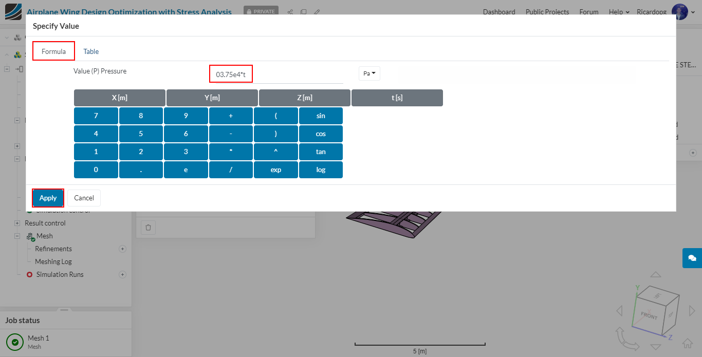
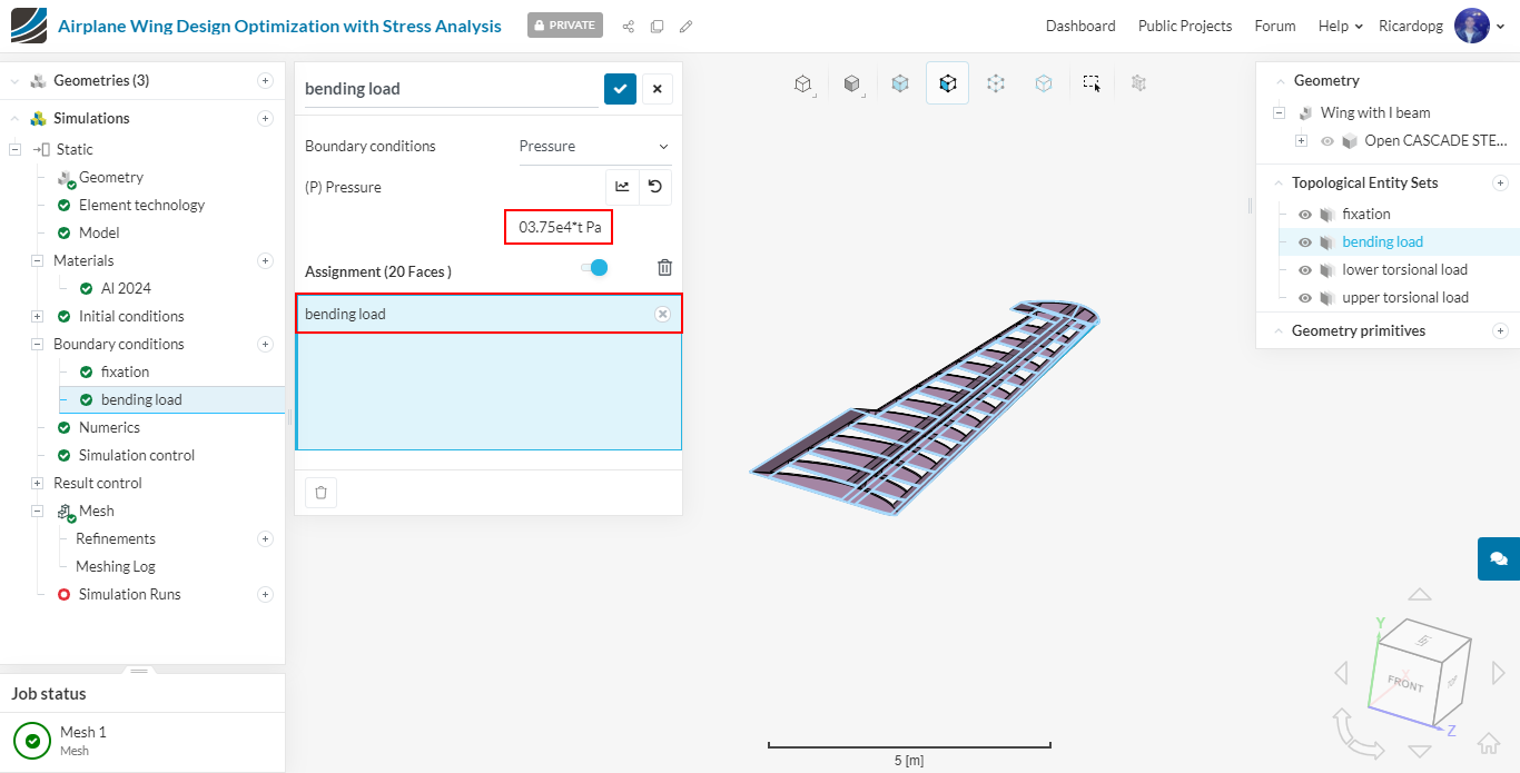
Click on Formula and input 3.75e4*t (this formula will apply pressure load of 3.75e4 Pa on all lower faces of the wing linearly over time. Time is multiplied since solver can’t automatically ramp the load over time).
Finally assign it to the bending load topological entity set:
Simulation control
Click on Simulation control and change change Maximum time step length to 0.25 seconds and Maximum runtime to 7200 seconds. You don’t have to worry with the number of processors, as it is automatically selected.

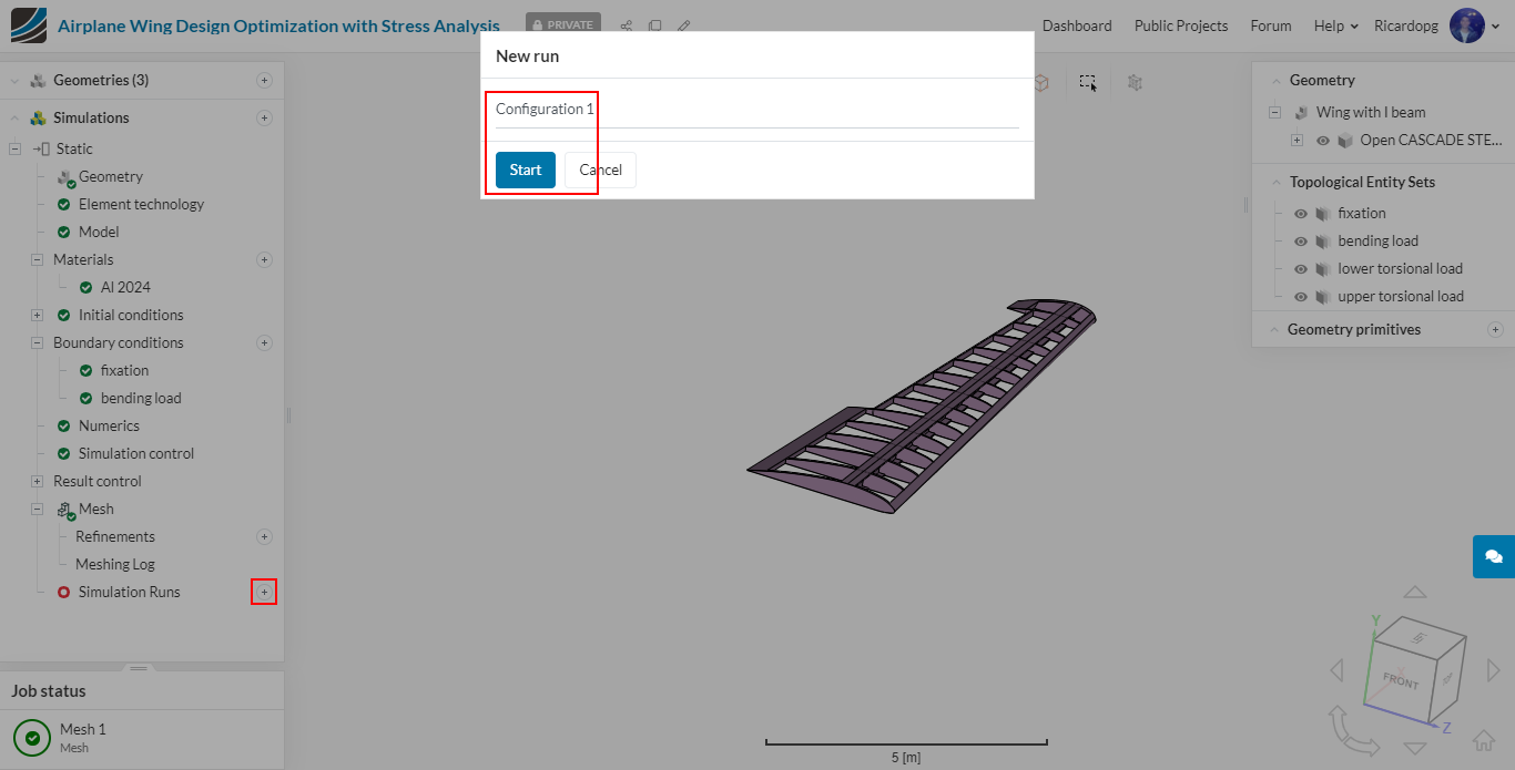
Navigate to Simulation Runs in the tree and click Start. Optionally, you can rename this first run Configuration 1.
Create Further Configurations
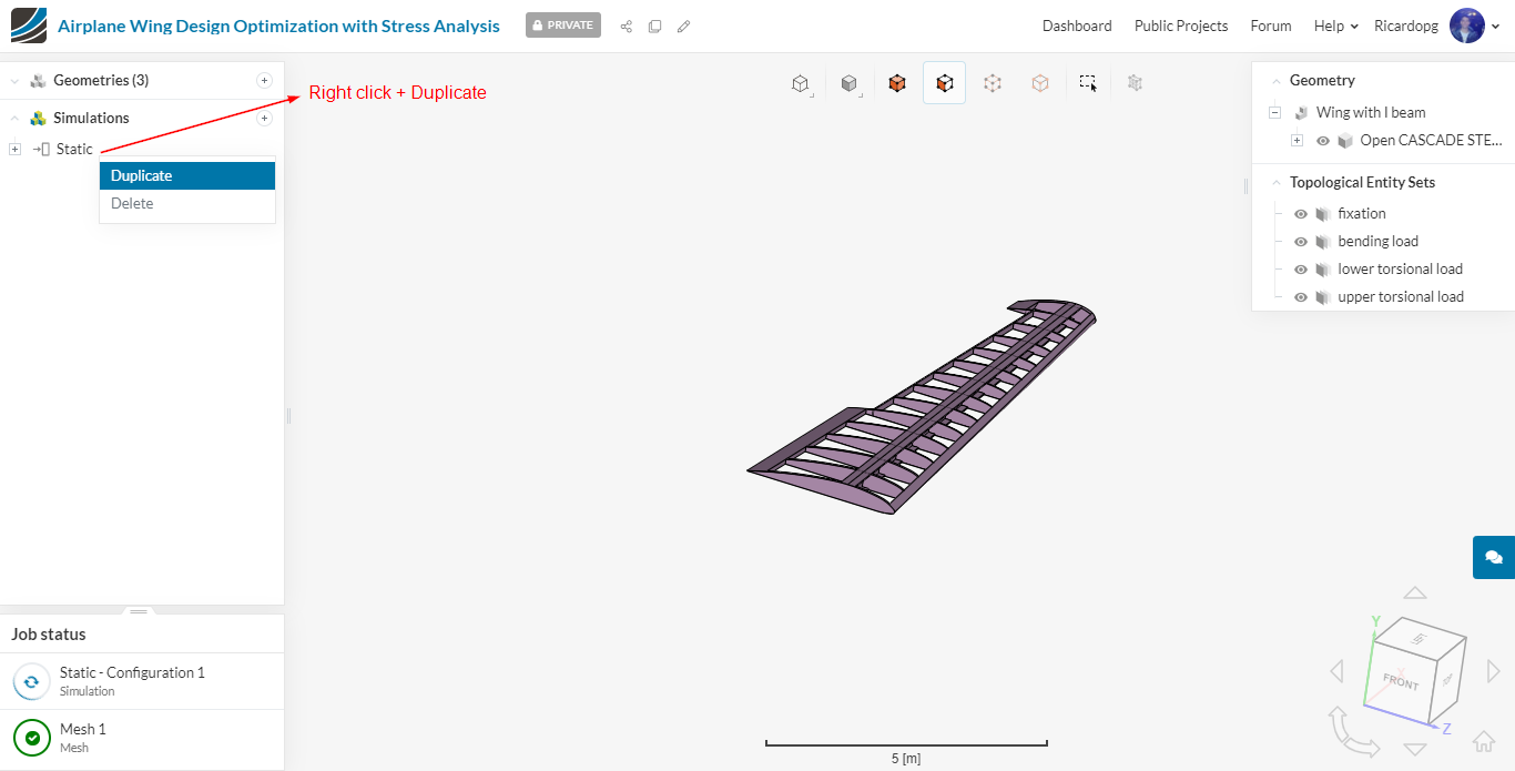
On SimScale you can run multiple jobs in parallel, therefore you can start setting up the other configurations. The easiest way to set up configuration 2 is by duplicating the first simulation’s setup:
Rename the second static analysis Wings with I beam torsional load.
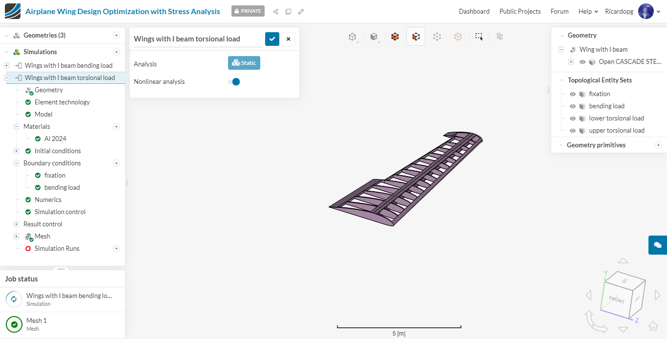
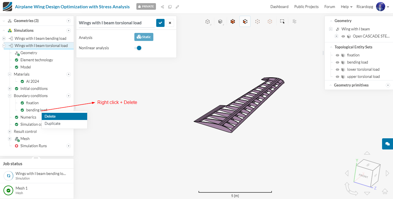
In terms of the set up, all you need to do is delete the bending load boundary condition and replace it by 2 other Pressure conditions:
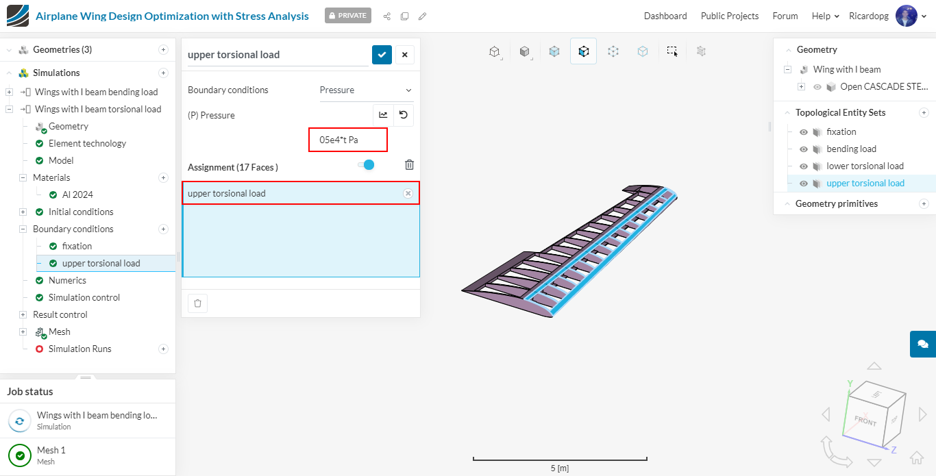
The first Pressure boundary condition will be named upper torsional load. The pressure formula for this one will be 5e4*t. Apply it to the upper torsional load topological entity set:
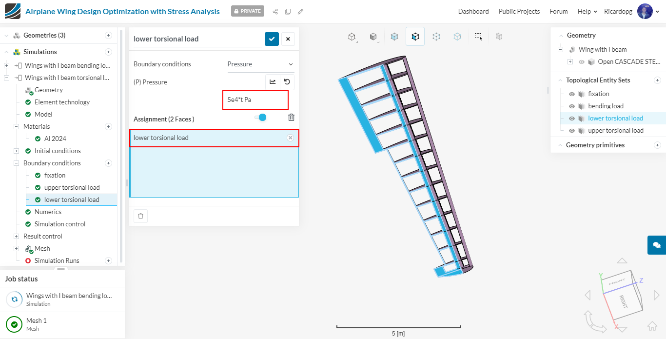
The second Pressure boundary condition will be named lower torsional load. The formula also is 5e4*t. Assign it to the lower torsional load topological entity set:
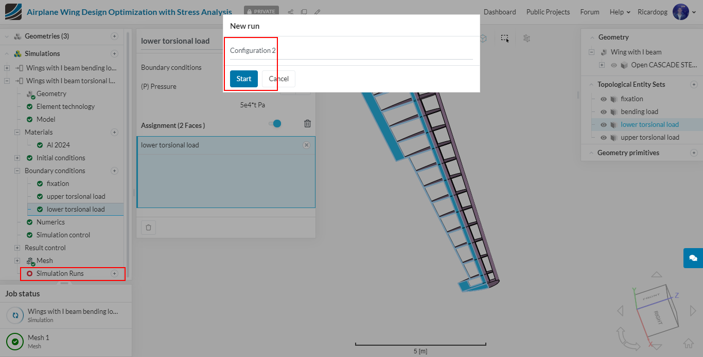
Create a new Simulation Run for Configuration 2.
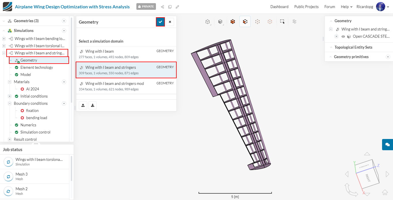
For all the other configurations with different geometries, duplicate the already created bending and torsional load simulations, change the Geometry assignment in the simulation tree and follow all the above steps in order to setup simulation cases for all the other configurations. For example, for the Wing with I beam and stringers:
Post-processing
When the simulations are finished, click on Solution Fields to access the post-processing environment. The post-processing was made for Configuration 1.
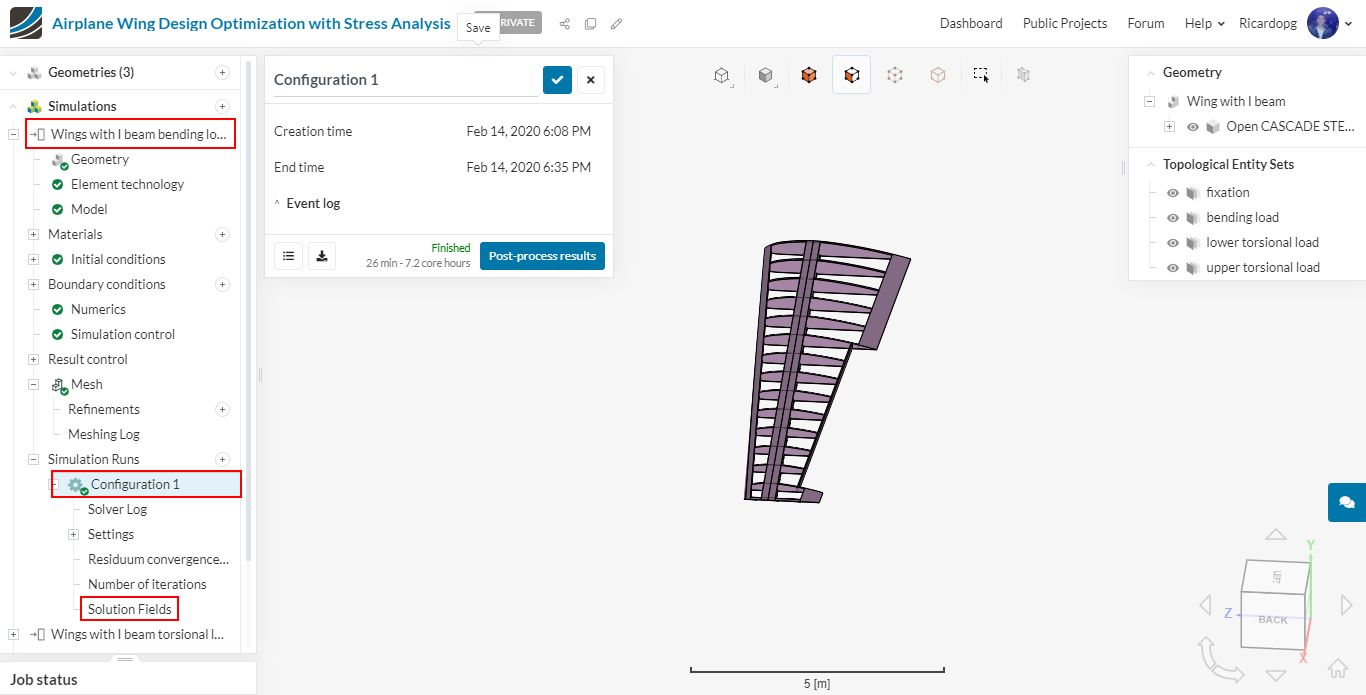
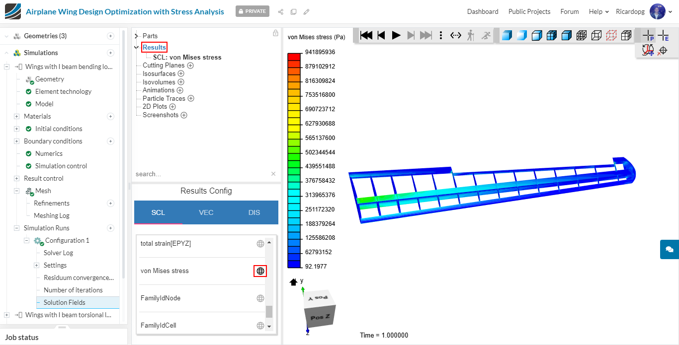
By clicking on the Results tab, a list of parameters appears. In this list, select von Mises stress:
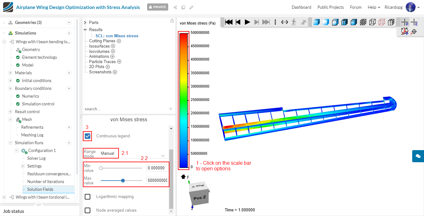
Adjust the scale bar’s range to 0-5e8:
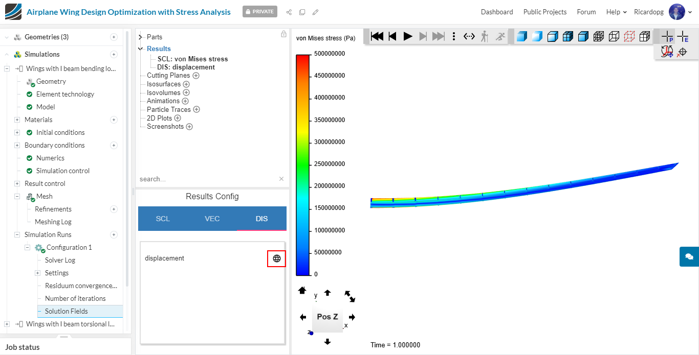
Now, back in Results, click on the DIS tab. You can enable/disable displacement. This filter shows how the wing would be after the load is applied.
- Wing with displacement off:
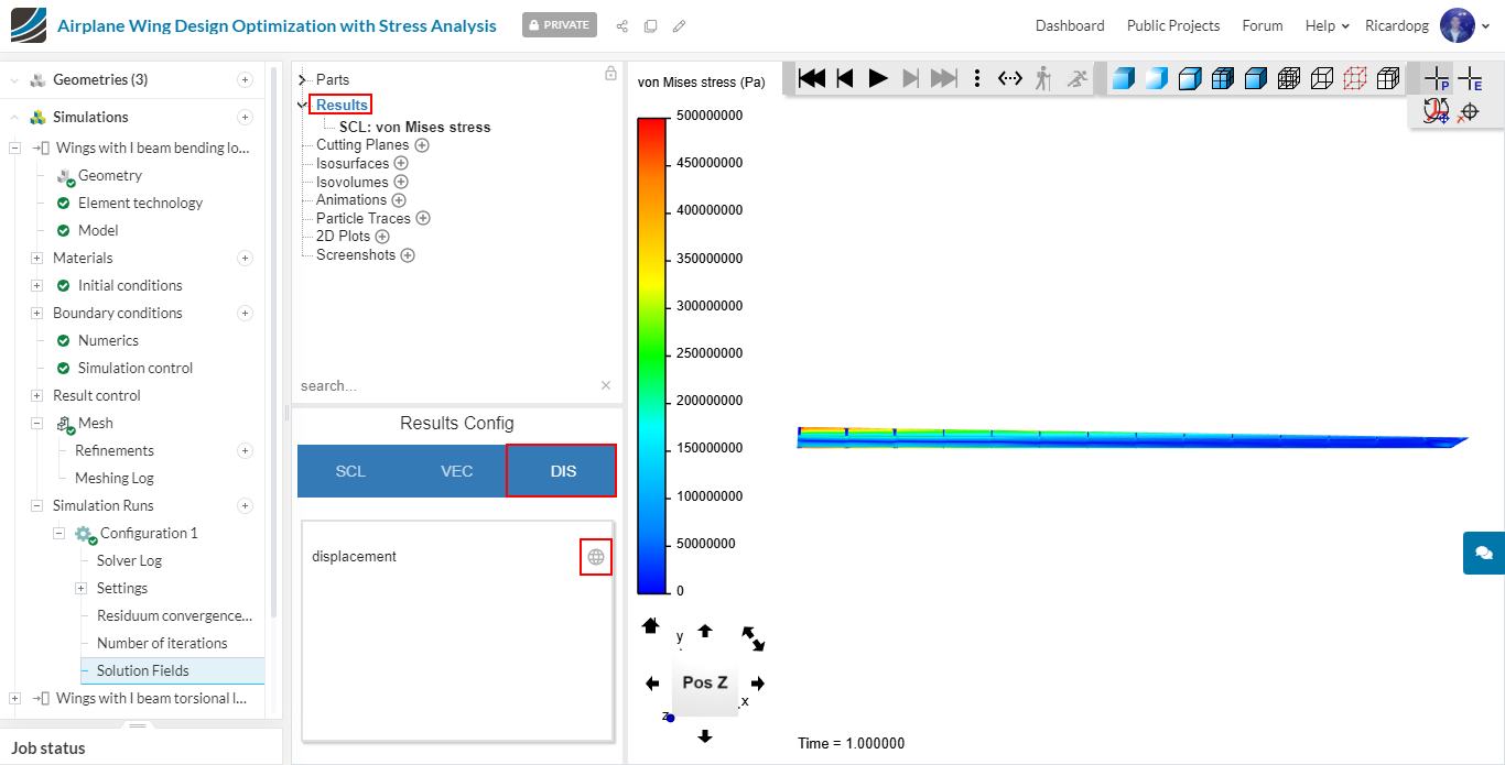
- Wing with displacement on:
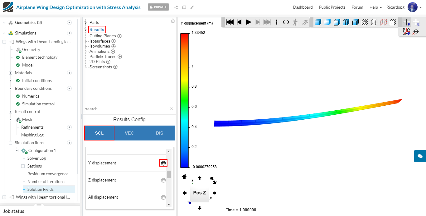
You can change the scalar to Y displacement to have a measure of how much displacement there is in the Y direction:
Now please follow the same post-processing guide for the other configurations and compare the results!