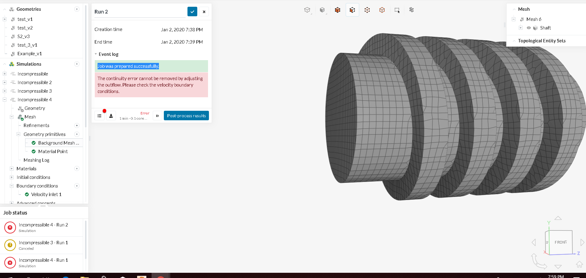
Thank you for the example. I tried and ran simulation.I tried to use simpler setup for by screw turbine shaft by enclosing it into region.And add 2 layers at inlet and outlet. I learned that inlet n outlet should be closed…so i add the layers…then the result was : Job was prepared successfully…The mesh generated result in image like this
… ALSO WITH AN ERROR : The continuity error cannot be removed by adjusting the outflow. Please check the velocity boundary conditions.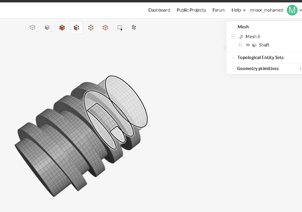
The initial geometry was https://a360.co/35aZC7u.
I want simulate a screw turbine with head 1m and angle of 18degree. Is it possible to include this as parameter in cad modeling part ???