Hello,
I am from Lawrence Technological University’s Formula SAE team. I have been working on simulating our current car (aero) to better understand how it will perform, as we as trying to perform CFD on last year’s car (no aero) to compare the two.
I uploaded my geometry, and created my mesh using the same settings but changing parameters for the different orientation (x,y,z are not the same between the 2 models). I created a mesh with 11 illegal cells, and it seemed to look pretty good. However, when I run the simulation I am getting lift and drag numbers that are higher than the car with aero.
Does anyone have any ideas of what I am doing wrong?
Please see the project at this link: SimScale
Mesh = OldCar Split
Simulation = OldCar or OldCar (Simscale Air Definition)
Thank you!
Morgan McCann
Hi Morgan (@mmccann )
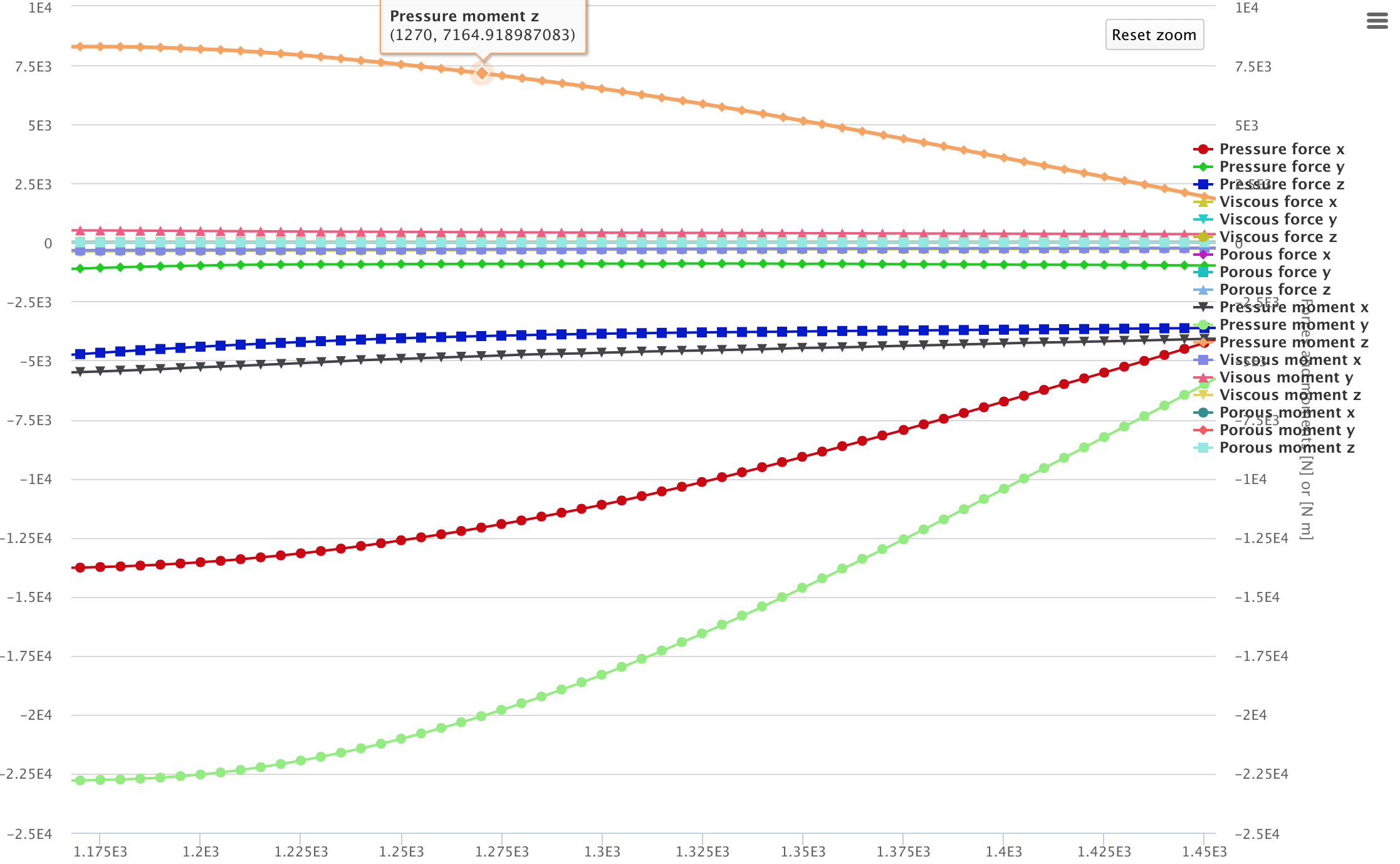
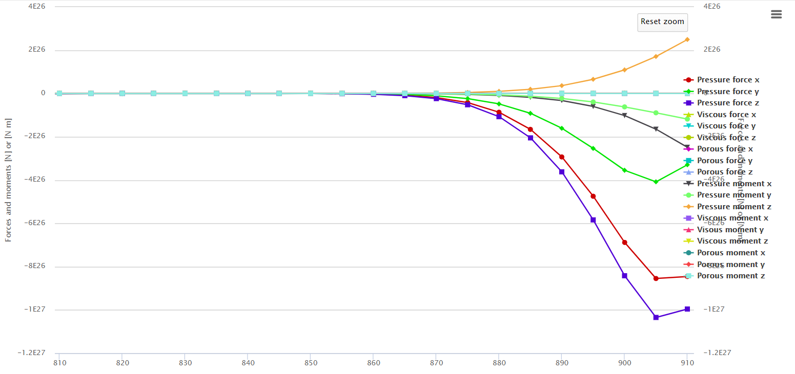
So I first checked convergence of the simulation using @pfernandez mesh and it converged well looking at the force plots. However, looking at your latest simulation’s (OldCar or OldCar (Simscale Air Definition)) they don’t converge, and when zoomed into the last time steps:
We see there is still a lot of movement in force values and therefore results are not converged. You might get away with just running for longer however if convergence still doesn’t happen you might have to adjust the numerics, starting with under-relaxation factors.
Hope this helps,
Darren
@1318980,
Thank you for replying!
I will try to run it longer!
Also, how do those factors affect the simulation? And where are they located?
Hi @mmccann,
They are located under “Numerics” and in particular “Relaxation factor for field p” and “Relaxation factor for equation U”.
Cheers.
Regards,
Barry
@mmccann, they affect the simulation by reducing instabilities. If you find running for longer isn’t improving convergence, then reducing the default values will be required. The downside to this is that not only are you reducing the effect of instability, but you are reducing the effect of stable iterations as well, therefore it will improve stability but increase the number of iterations required for convergence.
Hope this helps!
Darren
@1318980, that is very interesting. I will have to try that!
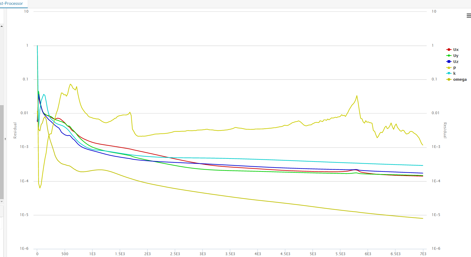
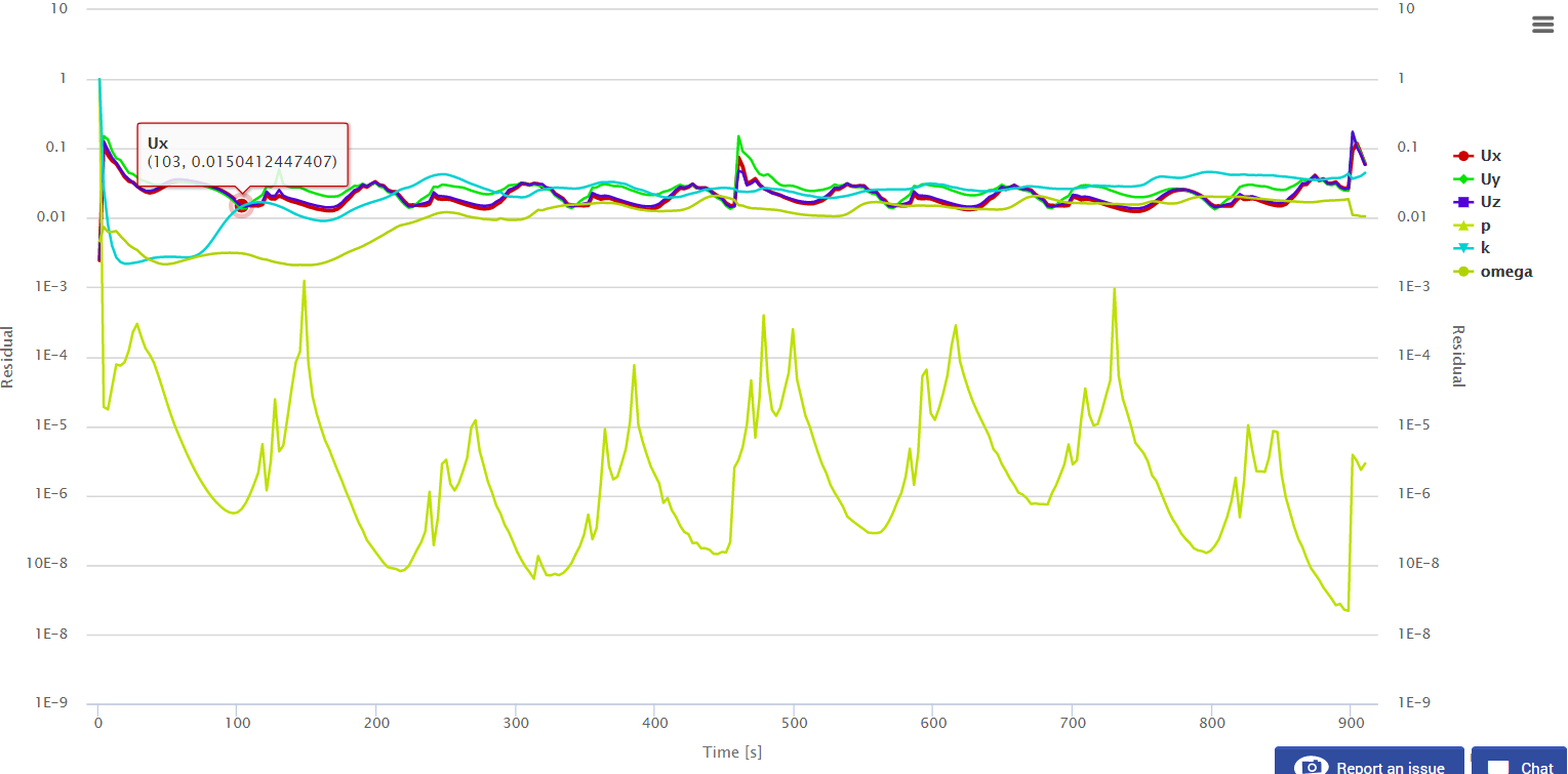
I ran another simulation for 7000 seconds, without changing the setting. The numbers make ALOT more sense now, however the convergence graph looks kind of weird. Especially for ‘p’.
I’m assuming changing those setting will help that convergence. I will change them and retry. What is a good amount to decrease the factor for P by (I changed it from 0.2 to 0.1 and have started another run)? Is that a value between 0-1 only?
Hi @mmccann,
yes, that sounds like a reasonable value, and yes between 0-1 are the valid inputs, with 1 being not relaxed and approaching 0 relaxed. You might find that it actually converges quicker in the above example since it is P that is holding off convergence.
Hope this helps,
Darren
Is there a formula for determining what P should be? Or is it a thing that comes with experience?
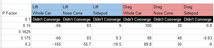
After starting a simulation with P = 0.1, I figured I should try some values in between. 0.1 didn’t converge when I changed the time to 7000 seconds, however 0.15 and 0.175 seemed to. I have started another run with P = 0.1625 to see if that helps.
Hi @mmccann, the relaxation factor should be the highest it can be but still get convergence, lower values should get the same results but in a slower time. so in the above example, I would say that 0.175 is the ideal value with the exception of nose cone drag being converged. I think the CFD master class session 2 goes into detail about this.
Kind regards,
Darren
*edit: weird that 0.1 didn’t converge, I think this is just a case of didn’t converge in the given iteration. I would expect convergence although more iterations might have been required.
Hello @1318980,
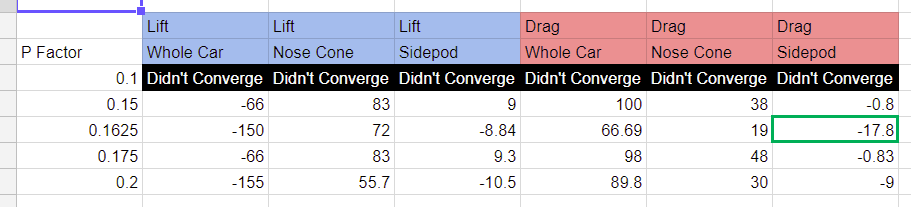
I will have to check out that master session! I updated my spreadsheet with the results of the simulation with p = 0.1625, below. All of these simulations were set to 7000 seconds. I am going to try to perform a new one with a time length of 9000 seconds, and see if I can reach convergence. Let me know what you think! It definitely doesn’t look converged to me.
Edit: Here is the project link, if you’d like to look at it: https://www.simscale.com/workbench/?pid=8968320798039816128#tab_1-0
Thank you!
Hi @mmccann, I think in a nutshell, looking at your results (force plots over time) I would say that none of these simulations converge. Some are closer to convergence but not converged. I would try reducing the relaxation factors of all fields a little maybe to say 0.3. I would hope that a good level of convergence would be gained by 2000 iterations and require a little more to get the tight convergence. If that doesn’t work I can make a copy of your project and see what can be done.
Let’s try to get this converging 
Best,
Darren
Hello @1318980,
I will start a simulation with all of the other relaxation factors set to 0.3, besides P. I will keep P at 0.1625. Did you mean to have all of them including P set to 0.3?
Another question: If I want to compare these results to the new car (with aero) do I need to use the same convergence settings, or is it simply look at the convergence graph and make sure the errors are close between the two?
Thank you! 
Hi @mmccann
I think to keep p at 0.1 and the others at 0.3.
We are not altering the criteria for convergence, just the stability to get convergence, so as long as both simulations converge then the comparison should be fair.
Kind regards,
Darren
@1318980, Thank you!
I have started a simulation with those inputs. It will take a while to run. When the simulation finishes, I will update you with the results of convergence.
Hello!
Changing the values to P = 0.1, and the rest equal 0.3 produced a diverging result.
Did changing all of the other values to 0.3 stop it from converging?
Thank you!
Convergence Plot:
Force Plot:
Hi @mmccann, i’ll copy your project over and have a look.
Kind regards,
Darren
HI @mmccann, really sorry for late response I am so involved with my Dissertation at the moment here is my copy of your project:
I think the initialise with the potential flow was making the stability worse, without it I got converged results.
Hope this helps,
Darren
Hello @131980,
That is amazing! Thank you so much! It is amazing how changing one setting can affect the whole result. What exactly does initializing the flow do to the result?
Good luck on your dissertation!
Hi @mmccann,
Thank you, one week to go and its falling into place!
basically, it’s initialising the flow field with results from the potential flow (a very basic CFD code) this can in some cases have a poor quality of results and therefore throw the calculation off dramatically. Most cases this improves convergence but in a small number of more complex flows this sometimes has detrimental effects.
Good luck with the rest of your project!
Darren
So, if I am understanding this the solver uses a super basic CFD code to get a very rough solution, and then takes that solution and plugs it into the “master” (for a lack of better term) solver, in hopes of increasing the rate of convergence?
If I was doing a simpler solution (say a rear or front wing only), it would probably help? However due to how complex the flow is around this car, the potential flow actually hurts the convergence?