Hello,
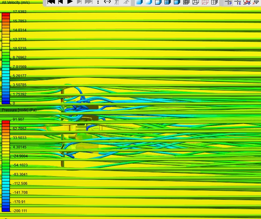
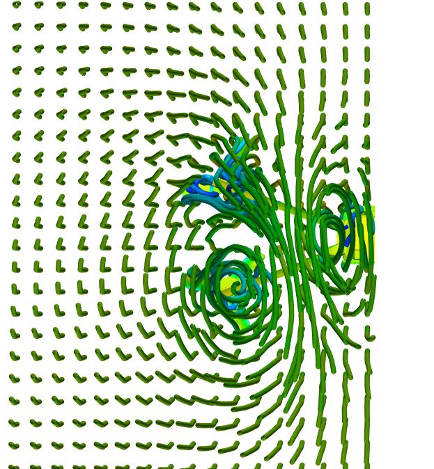
I am trying to simulate a drone during flight. I am having trouble setting up the rotating zones ( I know this because of the Velocity solution). The solution fields show a reduction of speed after the rotor.
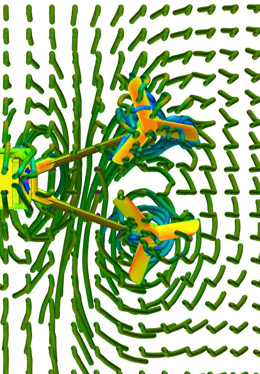
As I have 2 rotors I set up one as a rotating wall and one as a MRF, just to see the difference. Which one should I use to best simulate this rotor-wing interaction scenario? If i want to calculate the Lift and drag of the vehicle, should I put the Force center in the CG or where would it be best to locate it so SImScale can accurately measure the force.
Link: https://www.simscale.com/workbench/?pid=8319982879691374281&rru=1d6cacfa-f725-4979-90a4-19c7ecaca737&ci=01e957f1-6486-466a-8e1e-03e40067c606&ct=SOLUTION_FIELD&mt=SIMULATION_RESULT
The top right is supposed to be rotating CCW and the bottom right CW. Are my spinning directions wrong? How does SimScale define a positive rotation, with the right-hand rule?
Hi @dsafieh!
Correct, it’s the right-hand rule! In your case (and as y is in the “down” direction), looking from the top your one MRF is spinning in CW direction, you can also use the right-hand rule and hold it in the direction of the arrow indicated while editing the MRF. You can simply switch the rotation by switching the axis sign or you give the rotation a minus.
Best,
Jousef
Hi Jousef,
Perfect, so the rotations set are correct.
Do you know why the velocity of the flow decreases after the blade, it should increase.
Do you recommend changing the rotating wall to another MRF?
Thank you for the help.