I am trying to do a roller bearing simulation since we have no similar simulation in our library.
Unfortunately my simulation had an error. I would be happy if someone can have a look at it and give me some hints or make some comments about my settings
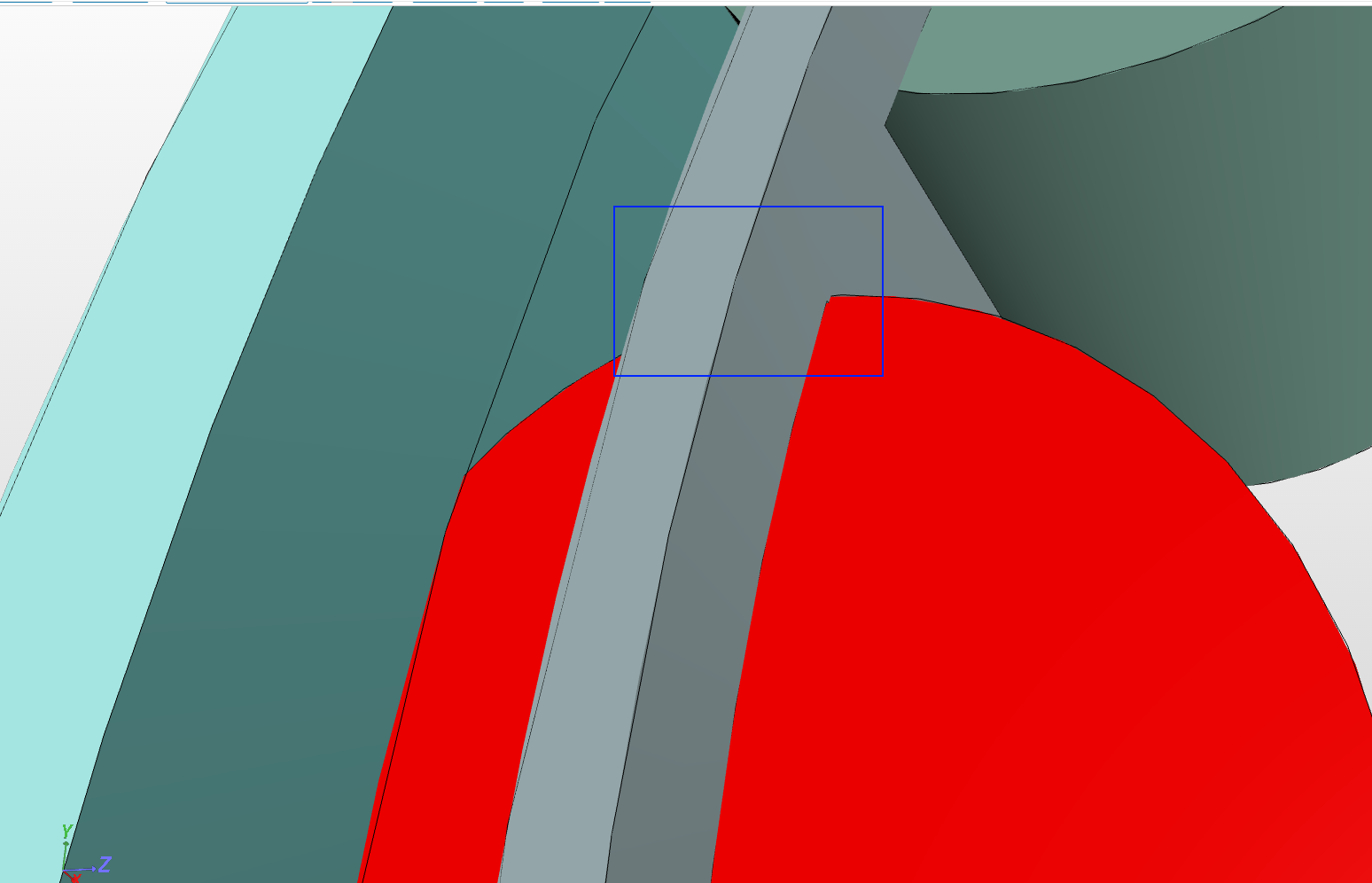
I looked in to your case. The error you are getting is due to low memory. There are certain things you can do. But before we dig in to those things, I would like to have your attention towards your geometry. Your geometry has intersecting solids, e.g. see one of the intersecting bearing in the figure below.
So first I would suggest to fix this before proceeding further. Next try to mesh it using Tetrahedral with local refinements so that you can refine only the contact regions but not the whole geometry. It is always a good practice to simulate first a basic coarse mesh and then go for a refined one. You can use the settings for the mesh as follows:
Also once you are editing the geometry, please also try to recenter your geometry to (0,0,0). This will help you afterwards. Furthermore, since your geometry is symmetric along yz plane, you can cut your geometry in to half in order to save simulation time.
thanks for jumping in. Well I just wanted to see if I can generate an animated output with a moving inner ring and a fixed outer ring trying to see the change in stress and strain within the rolling elements over time.
Thanks a lot for your interest. That will be great! But currently I am also working on it and good news is that it’s working out for now. All I have to do is to complete a simulation with bit finer mesh. I would say that let me come up with some solution and then you can take it over So that you don’t have to spend much time over it
@jousefm@BenLewis Just a quick update. I gave it a try. Below you can see the animation of the outcome with a coarse mesh:
I used frictional penalty contact with friction coefficient of 0.5. Also fictitious clearance of 0.0005 is applied on master surfaces i.e. inner and outer ring internal surfaces. The inner ring in this case is rotated 10 degree.
I am currently running cases with and without fictitious clearance on finer mesh. Once I am done I will forward my project link here
Super cool @ahmedhussain18! Looks almost like in Ansys.Well…I did not expect anything else
Concerning the fictitious clearance: Is this like an artificial distance we generate? And does the solver necessarily needs this fictitious clearance in order to calculate the solution or why is the geometrical “gap” (if we have one) not enough?
Yes, fictitious clearance is like an artificial clearance. I used it to compress the bearings in order to make it look more realistic and also to attain stability.
Solver necessarily doesn’t need this. I first ran the simulation without clearance and it also worked, took more time but the results were not quite good due to coarse mesh and little gap between the contact surfaces (specially outer ring one).
It is not about geometrical gap since I need to compress it rather then creating a gap. So in other words, if you even have a gap between two contacting surfaces, then rather then modifying your geometry you can use fictitious clearance to artificially remove the gap
@jousefm@BenLewis Finally at the end of the day I managed to finish final case with finer mesh. This time it is rotated 45 degree. Below you can see the animation of vonMises stress and displacement magnitude:
Hi @all,
I have got a similar problem to this which has been giving me a hell of a time. My model is the kind without rings in which I am to find the stress in the cage under a planetary motion (rotational velocity = 11000 rpm).

 Glad to have you guys

 Looks almost like in Ansys.Well…I did not expect anything else