Results show slot gap not working as well as intended, bad rear wing design or more accurate BL capture needed?

Hi, so I have finally got round to completing my first simulation of a rear wing I’m working on.

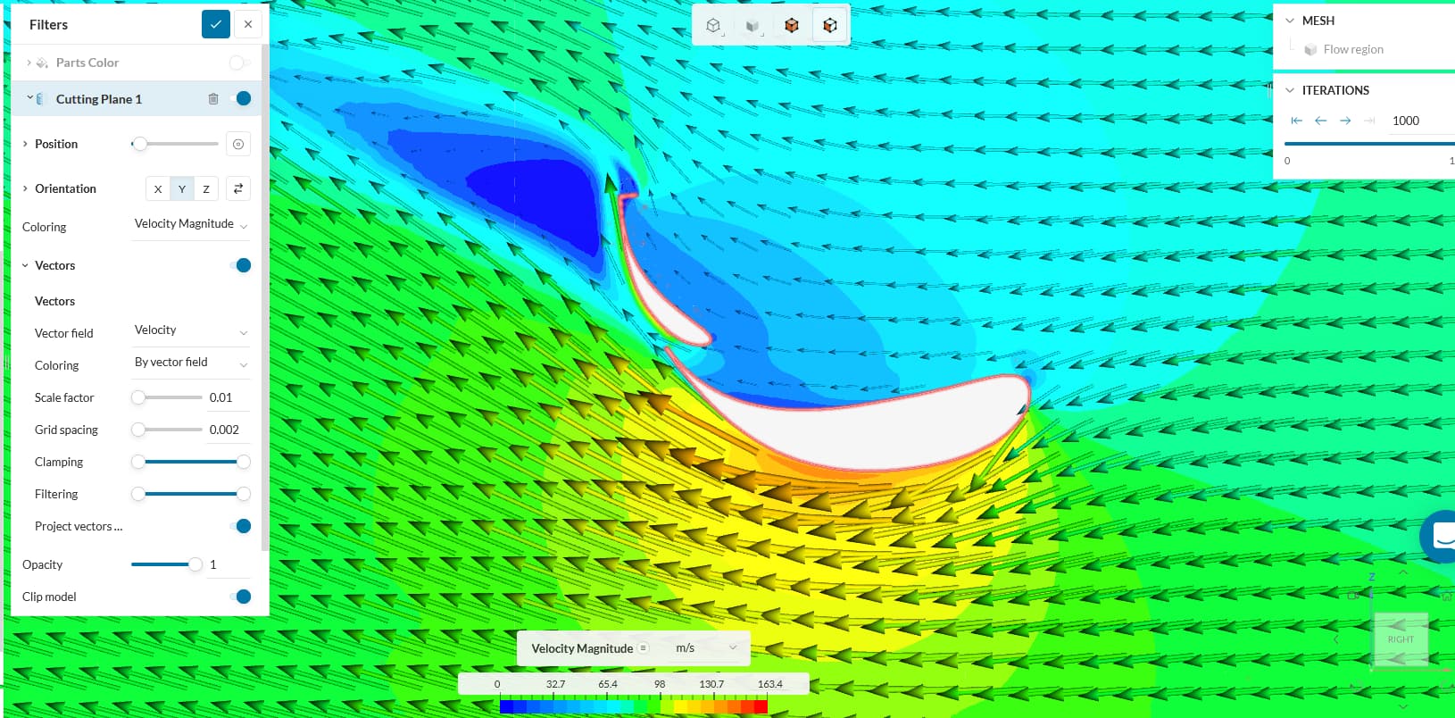
Unfortunately, the central part of my rear wing doesn’t seem to be going too well, as it seems im getting very bad flow separation, even more so than I first imagined, fully aware of how aggressive of a camber the central profiles are.

My question is this, do the results seem pretty plausible and its just simple a poor design, if so, is it a badly designed flap in terms of how its leading edge interacts with the main plane trailing edge, should the slot gap be bigger or narrower, flap section moved further forward or back, is the slot gap doing a good job of energising the suction surface?

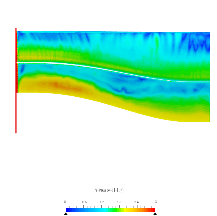
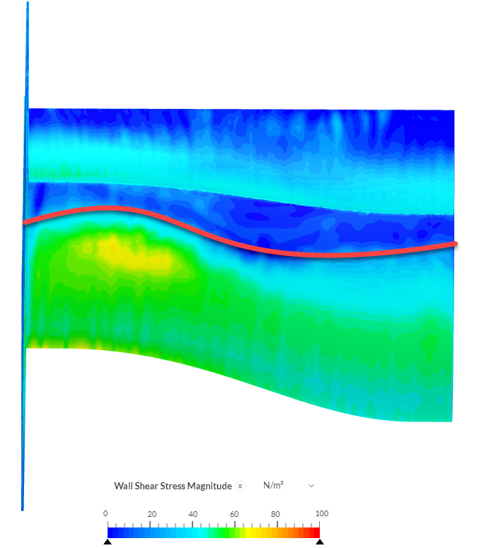
Or is it mainly to do with my mesh? This is still my first mesh/guess with regards to estimating the boundary layer, and it seems it was a bad one, as probe point one is on the pressure side of the main plane at a height equal to the top prism layer, and the flow velocity there was more like 50% of freestream rather than 99%, indicating my boundary layer is a lot bigger than I initially thought. Again, this was my first mesh, so I haven’t had a chance to make a second iteration, using wall shear stress values calculated from the first run to make a better boundary thickness and first cell height guess with some MATLAB code.

Is it also to do with the initial conditions I specified for turbulent kinetic energy and specific dissipation rate at 0.7776 m^2/s^ and 0.362/s respectively?

I’m using SST model, with full resolution model on the two profiles and wall function on the endplate. I’m testing the wing at 72m/s (~160mph). Funnily enough the wing still makes more downforce than the wing I wanted to compare my results with, but obviously it would be nice to make it work a bit better.

Here is the project for anyone to have a gander through the results and mesh/initial conditions to see if im doing something wrong. Maybe its a mixture of both, poor design and poor initial mesh/input conditions?

Hi shutchinson

first of all a very interesting project of yours. And also I think for a first iteration the wing looks pretty good.
Since you are using K-w Menter SST as a turbulence model and most of the y+ values of the wing is below 3. But since you used a full-resolution model for the wing surfaces., i would suggest switching to the wall function. As the y+ value is not under 1 for the entire wing and adjusting the mesh to be below 1 for the entire wing will cost much more cells, which on a computational level will not be efficient. and still the viscus sublayer is well captured by the turbulence model.

In regards to your wing designs, your image is typical for a wing where the slot gab itself is working properly, but the first element is stalling beforehand. Taking a look at the Wall Sher Stress (WSS) we can one where the WSS drops significantly. This line indicates a detachment of the flow. Thus I would suggest moving the slot gap further to this line, or changing the main profile to a less aggressive one.

Please let me know if these changes will help you with your design.

Looking forward to your next iteration.

Best regards
Sebastian

1 Like

Hi @SBlock thank you for your input with regards to interperating these results.

So before I create a new mesh, if im wanting to instead use wall functions on the wing surfaces, do I still need to be defining the first cell height or growth ratio to make sure prism layers are capturing the full thickness of the boundary layer, based on a rough estimate of what I expect the boundary layer thickness to be?

ie, I would use the CFD online y+ calculator, with a target y+30, and based on this initial result, will most likely double my initial boundary layer thickness guess, and then use that first cell height, but this time only use 5-10 prism layers for the mesh to capture the boundary layer?

Edit: Okay so I’ve had a go trying to generate a mesh for the wall function boundary condition on the wing, y+ calculator estimated a first cell height of 3e-4 (multiplying the y+ calculator output by 2 since it gives centroid height) for a y+ of 30, and no matter how low I reduce the small feature suppression, I’m only getting 2 prism layers, I even tried reducing the specified layer number from 10 down to 8 but still no luck, I’m guessing it’s also to do with the overall relative thickness, and the default 0.4 isn’t enough?

Hi shutchinson

When using wall function models the wall turbulence model will try to calculate the right boundary layer height. Thus it’s important to ensure two things.
Correct Y+ region y+ < 3 or y+ >30
Good gradient from the last boundary layer cell to the first volume cell.

Based on my experience, I suggest aiming for a low +y mesh when simulating wings.
This is due to the fact that for a high y+ mesh a more coarse mesh is needed, to keep the aspect ratio of the cells in a good quality range.
this leads to the fact that the CAD of the wing will have a bad resolution.
We can easily capture this with a low +y mesh (y+<3).

Best regards
Sebastian

Also, if I may add one more thing to consider.

From memory, tetrahedral meshes don’t tend to perform well for slender body external aerodynamics, wrt separation point and viscous effects. I personally would concentrate on the hex-dominant mesher for this type of problem.

Best,
Darren